
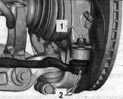
To protect the thread, leave the nut on the pin screwed on for a few turns. Press out the end of the transverse steering rod from the hub bearing housing using the ball joint puller "T40010 A". Then unscrew the nut.
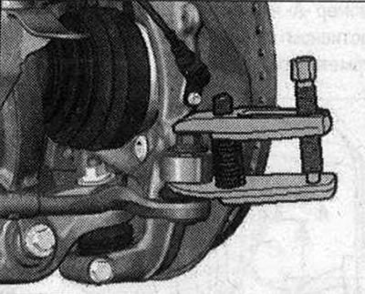
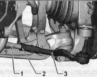
Ensure that both arms of the puller lever are parallel to each other at the moment of maximum force application; correct the position if necessary. For subsequent installation, mark the position of nut "2" on the transverse steering rod "1". Holding the steering rod end "3" from turning, loosen the lock nut "2".
Open and remove spring clamp "3" using hose clamp pliers "V.A.G 1921". Remove clamp "1" and remove bellows "2" outward from the power steering mechanism.
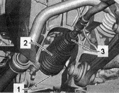
Unscrew the end of the transverse steering rod "3" and nut "2" from the transverse steering rod "1". Pull off the corrugated boot together with the spring clamp from the transverse steering rod. If there are visible signs of corrosion, damage, wear or contamination of the toothed rack, the steering gear is replaced as an assembly. If there is no visible film of grease on the toothed rack, the steering gear is also replaced as an assembly.
Installation
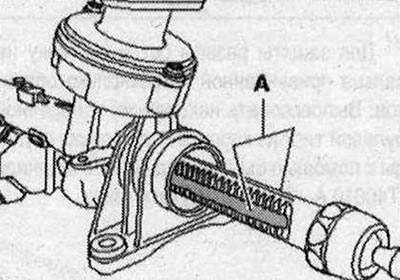
Before installation, apply the grease supplied with the repair kit to the toothed rack. It is strictly forbidden to use any other grease. To do this, turn the steering mechanism in both directions until it stops. For better clarity, the steering mechanism is shown removed in the figure. Apply grease to the toothed rack from the side of the teeth "A" and from the side of the pressure stop.
Set the steering wheel to the "straight ahead" position. Put new clamps and bellows on the tie rod. Screw on nut "1" and tie rod end "3" up to the marking applied before removal. Tighten nut "2" with a torque wrench. At the same time, hold the tie rod end "3" from turning. The sealing surfaces of the bellows/power steering mechanism must be degreased during installation. Slide the bellows with a new clamp onto the steering gear housing. Ensure that the bellows is correctly positioned on the power steering mechanism. The bellows must fit in the groove and along the perimeter of the power steering mechanism.
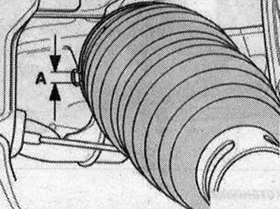
Installing the clamping clamp: Ensure that the dimension "A" is max. 5.7 mm. The dimension "A" should not exceed 5.7 mm, otherwise there will be problems with tightness.
Clamp clamp "1" using the steering gear clamp pliers "VAS 6199". Fasten spring clamp "3" to bellows "2" using hose clamp pliers "V.A.G 1921". Installation in reverse order. It is necessary to adjust the wheel alignment angles.
[Read the original source on the website «AUDIMANUAL»]