
Table of contents: Removal and installation the… ↓ Removal and installation, tensioning… ↓
1. Timing belt installation details are shown in the illustration.
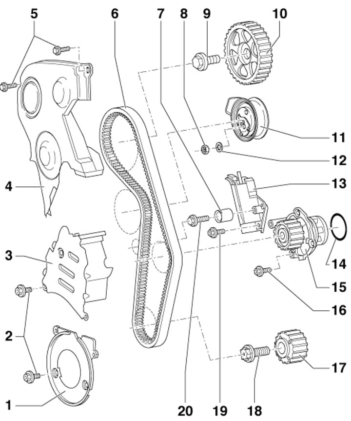
10.1 Timing Belt Installation Details 1. Lower timing belt guard; 2. Bolts for fastening casings 1 and 3, 10 Nm; 3. Timing belt center cover; 4. Upper timing belt cover; 5. Casing mounting bolts 4, 10 Nm; 6. Timing belt; 7. Intermediate roller; 8. Tension roller nut, 27 Nm; 9. Gear mounting bolt 10, 65 Nm; 10. Camshaft gear wheel; 11. Tension roller; 12. Washer nut 8; 13. Timing belt tensioner; 14. Water pump sealing ring; 15. Coolant pump; 16. Pump mounting bolts 15, 15 Nm; 17. Crankshaft gear; 18. Gear mounting bolt 17, 90 Nm, then tighten to an angle of 90°; 19. Tensioner mounting pains, 15 Nm; 20. Roller mounting bolt 7, 25 Nm
Removal and installation the tensioner
2. Set the radiator frame to the service position (see Section 6).
3. Remove the top engine cover by moving it upwards (see illustration 5.21).
4. Remove the alternator drive belt (see Section 7).
5. Remove the bolts (1 in illustration 7.1) and remove the alternator belt tensioner.
6. Remove the bolts (5 in illustration 10.1) and remove the upper timing belt cover.
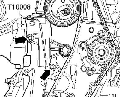
7. Remove the bolts (the top three arrows in the illustration) and remove the middle timing belt cover.
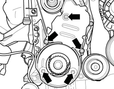
10.7. Bolt for fastening the middle and lower timing belt protective covers
8. Use a clamp to secure the tension roller from falling (see illustration).
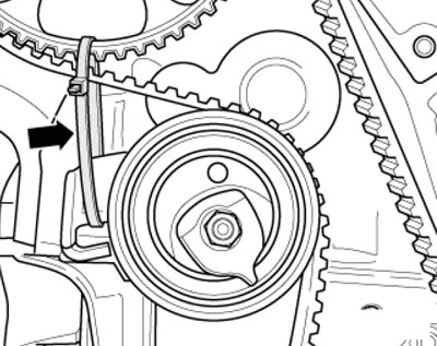
10.8. Fixing the tension roller
9. Press the timing belt tensioner with a hex key with a uniform, light force in the direction of the arrow (see illustration) until it is possible to secure the tensioner piston using the T10008 insert plate. Insert this plate.
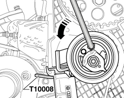
10.9. Tensioner lock
Note: The timing belt tensioner is coated with oil vapor and should be compressed slowly and evenly. Too much compression force may damage the tensioner.
10. Remove the bolts (see illustration) and remove the timing belt tensioner.
10.10. Timing belt tensioner fastener
11. Installation is carried out in the reverse order of dismantling the components. Please note the following information.
12. After installing the tensioner, loosen the clamp that prevents it from falling, loosen the nut (1 in the illustration) and tension the timing belt as described in paragraphs 31-36.
10.12. Loosening the tensioner nut
13. The tightening forces for the fasteners are indicated in the captions to Illustration 10.1. Apply thread varnish to the threads of the bolts securing the middle timing belt cover before tightening them. Removing the timing belt from the camshaft gear.
14. Follow the steps in paragraphs 2-4 and 6.
15. Turn the crankshaft by the bolt of its gear wheel clockwise so that the piston of the first cylinder is at the TDC of the end of the compression stroke. In this case, the marks on the gear wheels of the crankshaft and camshafts should be opposite the TDC marks (see illustration).
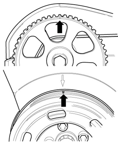
10.15. The marks on the gears coincide with the TDC marks
16. Press the timing belt tensioner with a hex key with a uniform, light force in the direction of the arrow (see illustration 10.9) until it is possible to secure the tensioner piston using the T10008 insert plate. Insert this plate.
Note: The timing belt tensioner is coated with oil vapor and should be compressed slowly and evenly. Too much compression force may damage the tensioner.
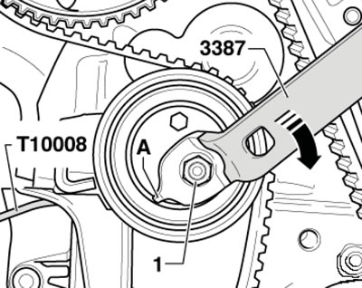
17. To loosen the timing belt, loosen the nut (1 in illustration 10.12) tension roller and turn the eccentric with key No.3387 in the direction of the arrow. Remove the timing belt from the camshaft gear.
Note: The thrust projection (A) of the eccentric must not be bent.
Caution: When turning the camshaft with the timing belt removed, none of the pistons should be at TDC.
18. After finishing the work, align the marks on the gears with the timing marks (see illustration 10.15) and make sure that the tensioner is fixed with plate No. T10008. Put on the timing belt in the sequence: water pump → tension roller → camshaft gear. Tension the timing belt as specified in paragraphs 31 - 36.
19. Installation is performed in the reverse order of component dismantling. The tightening forces for the fasteners are indicated in the captions to Figure 10.1.
Removal and installation, tensioning of the timing belt
20. Follow the steps described in paragraphs 2-6.
21. Turn the crankshaft by the bolt of its gear wheel clockwise so that the piston of the first cylinder is at the TDC of the end of the compression stroke. In this case, the marks on the gear wheels of the crankshaft and camshafts should be opposite the TDC marks (see illustration 10.15).
22. Holding the crankshaft from turning by the central bolt, unscrew the bolts (16 in illustration 7.1) fastenings of the crankshaft pulley and remove it.
23. Remove the middle and lower timing belt guards (see illustration 10.7).
24. Press the timing belt tensioner with a hex key with a uniform, light force in the direction of the arrow (see illustration 10.9) until it is possible to secure the tensioner piston using the T10008 insert plate. Insert this plate.
Note: The timing belt tensioner is coated with oil vapor and should be compressed slowly and evenly. Too much compression force may damage the tensioner.
25. To loosen the timing belt, loosen the nut (1 in illustration 10.12) tension roller and turn the eccentric with key No.3387 in the direction of the arrow.
Note: The thrust projection (A) of the eccentric must not be bent.
26. If the belt being removed is intended to be reused, mark the direction of rotation on it with chalk or a felt-tip pen. Remove the timing belt.
Caution: When turning the camshaft with the timing belt removed, none of the pistons should be at TDC.
27. Place the timing belt on the crankshaft toothed wheel, taking into account the direction of the belt run (if a previously used belt is being installed).
28. Install the lower timing belt cover.
29. Install the crankshaft pulley onto the toothed wheel.
30. Align the marks on the gears with the timing marks (see illustration 10.15). Make sure the tensioner is fixed with plate No. T10008 and install the timing belt in the sequence: water pump → tension roller → camshaft sprocket. Tension the timing belt as described in paragraphs 31 - 36.
31. Turn the eccentric using key No.3387 in the direction of the arrow (see illustration) and, holding the eccentric in this position, remove the insert plate No. T10008.
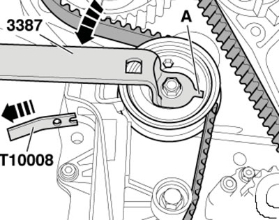
10.31. Removing plate No. T10008
Note: The thrust projection (A) of the eccentric must not be bent.
32. Turn the eccentric in the direction of the arrow (see illustration) so that a template (2) with a size of a=8 mm can be passed between the tension lever and the tensioner body (for example, a drill). Fix the eccentric in this position and tighten the tensioner nut (1) to 27 Nm.
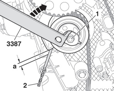
10.32. Setting the gap between the lever and the tensioner housing
33. Turn the crankshaft by the gear bolt clockwise 2 turns until the crankshaft returns to the TDC position (the marks on the gears must match the TDC marks).
34. Using a template (2 in illustration 10.32) check the dimension (a) between the tension arm and the tensioner body. This dimension should be 610 mm.
35. If the specified value is not reached, press the timing belt tensioner with an Allen key with a uniform, slight force in the direction of the arrow (see illustration 10.9) until it is possible to secure the tensioner piston using the T10008 insert plate. Insert this plate.
Note: The timing belt tensioner will be coated with oil vapor, it should be compressed slowly and with uniform force. Too much force when compressing may damage the tensioner. Then loosen the nut (1 in illustration 10.12) and repeat the tension (go to paragraph 31).
36. Install the middle and upper timing belt covers.
37. Further installation is carried out in the reverse order of component dismantling. The tightening forces for the fasteners are specified in the captions to Illustration 10.1. Use new crankshaft pulley mounting bolts. Apply thread sealant to the threads of the lower and middle timing belt cover mounting bolts.