



Note: The following describes the operating principle of a typical gasoline engine control system. The features of a diesel engine control system are described in the subsection below.
Since the fuel system is part of the engine management system, which also combines the ignition and exhaust gas toxicity reduction systems, it is not possible to consider them separately. Some parts of the 1.8 l and 2.0 TFSI engine management system located in the engine compartment are shown in Illustrations 2.1 a-b.

2.1a. Components of the 2.0 TFSI engine management system located in the engine compartment 1. MAF sensor; 2. Pre-catalytic lambda probe; 3. Post-catalytic lambda probe; 4. ECT sensor; 5. Intake camshaft control valve No.1; 6. Fuel pressure control valve; 7. Fuel injection pump; 8. Fuel pressure sensor in the low-pressure circuit, 15 Nm; 9. Intake manifold flap actuator; 10. SCR sensor; 11,12. 6-pin connectors of lambda probes 2 and 3; 13. Evaporative Evaporative Canister Purge Valve; 14. ECM; 15. Boost pressure sensor; 16. Throttle body with actuator; 17. IAT sensor; 18. Fuel pressure sensor, 22 Nm; 19. SMR sensor; 20. Ignition coils; 21. Turbocharger with air circulation valve; 22. Solenoid valve for regulating the boost pressure
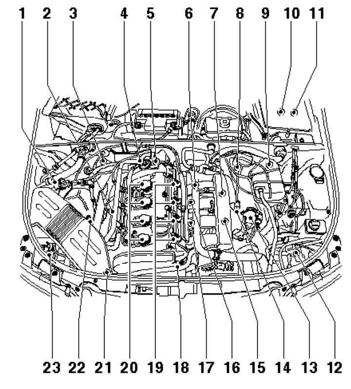
2.1b. 1.8L engine management system components located in the engine compartment 1. Evaporative Evaporative Canister Purge Valve; 2. Pre-catalytic lambda probe; 3. Post-catalytic lambda probe; 4. Combined valve for mixing additional air; 5. ECT sensor; 6. SCR sensor; 7. Additional air inlet valve; 8.9. Connector holder; 10,11. Mounting block in the water drainage channel; 12. Boost pressure sensor; 13. Throttle control unit; 14. IAT sensor; 15. Turbocharger air circulation valve; 16/17. Knock sensor #1/#2; 18. SMR sensor; 19. Injectors; 20. Ignition coils; 21. Solenoid valve for regulating the boost pressure; 22. MAF sensor; 23. Additional air pump
Fuel is drawn from the fuel tank by an electric fuel pump and delivered through a fuel filter to the fuel rail. The pressure regulator ensures that the pressure in the fuel system is maintained at a certain level (see Specifications).
Fuel is injected in pulses through electrically controlled injectors into the intake ports located directly in front of the engine intake valves (on FSI engines, fuel is injected directly into the cylinders). The engine control unit (ECM) determines the optimum ignition and injection timing, as well as the amount of fuel injected, in coordination with other vehicle systems. The high voltage for sparking is generated by the ignition coils mounted above the spark plugs, as signaled by the ECM (except for the 1.6 l engine, it uses an ignition module connected to the spark plugs by high-voltage wires).
The crankshaft position sensor (CPS) provides the control unit with information about the crankshaft speed and its exact position. This information is used to determine injection and ignition timing. The CPS sensor is located on the rear of the engine and operates on the Hall effect, scanning the teeth of the rotor mounted on the crankshaft.
The camshaft position sensor (CMP) is located on the end of the cylinder head and operates similarly to the CMP sensor, scanning the toothed rotor at the end of the intake camshaft. The CMP sensor, together with the CMP sensor, is used to determine the TDC of the piston of the first cylinder, dynamic adjustment of the timing phases (by means of an electromagnetic valve and an intake valve phase regulator), selective control of detonation in cylinders and for determining the injection sequence.
The air required to form the working mixture is sucked in by the engine through the air filter and enters through the throttle valve and the intake manifold to the intake valves. The amount of air sucked in is regulated by a throttle valve with an electric drive, controlled by signals from the gas pedal position sensor. Thanks to electronic control, the mass air flow in the intake manifold can be set independently of the gas pedal position, and at idle speed the throttle valve opens to the angle required to set the required crankshaft speed. The mass of air sucked in is determined by a hot-wire air flow meter or an intake air pressure sensor.
Knock sensors (KS), one for each of the two adjacent cylinders, are screwed into the side of the cylinder block and prevent the occurrence of shock combustion of fuel. Thanks to this, the ignition timing is maintained at the detonation limit, which ensures better use of fuel energy and, thus, a reduction in fuel consumption.
Information from other sensors and control voltages supplied to the actuators ensure optimal engine operation in any situation. If some sensors fail, the control unit switches to the emergency program mode to prevent possible engine damage and ensure further movement of the vehicle. In emergency mode, the injectors operate simultaneously, 2 times per working cycle.
The fuel tank ventilation system consists of a gasoline vapor absorber and an electromagnetic valve. The absorber concentrates fuel vapors that form in the tank as a result of fuel heating. During engine operation, fuel vapors are pumped from the absorber and participate in the formation of the working mixture.
Reduction of exhaust toxicity is achieved with the help of a 3-function catalytic converter and lambda probes (before and after catalytic converter).
Also, to eliminate leaks of unburned hydrocarbons into the atmosphere, a crankcase ventilation system (PCV) is used. Gases and oil vapors formed in the crankcase enter the intake manifold (due to the pressure difference - it is higher in the crankcase) and burn in the cylinders along with the fuel.
In order for the numerous electronic control units to exchange data with each other, these units are connected by a high-speed CAN data bus. The CAN bus consists of two lines, which reduces the amount of wiring. Each control unit can simultaneously transmit and receive data, but each specific unit reads only the data it needs from the CAN bus.
Features of the diesel engine control system
Diesel engines are controlled by an electronic system similar to that of petrol engines (see above).
When a diesel engine is running, clean air is sucked into its cylinders and compressed to high pressure. The air temperature rises above the ignition temperature of diesel fuel. The fuel is injected into the cylinder a little ahead of its time and ignites spontaneously. Thus, spark plugs are not used to ignite the fuel in a diesel engine.
When the engine is cold, the compressed air temperature may not reach the value required for ignition. In this case, additional preheating is required. For this purpose, a glow plug is installed in each cylinder, which heats the combustion chamber. The duration of heating depends on the ambient temperature and is regulated by the engine control unit and the preheating relay.
Before entering the injection pump or pump-injectors, the fuel is cleaned of contaminants and water in a heated fuel filter. Therefore, it is important to remove water from the fuel filter or replace it in accordance with the requirements of the maintenance schedule (see Chapter 1).
To increase power, all diesel engines use turbocharging.
Some parts of the 4-cylinder engine control system located in the engine compartment are shown in Illustrations 2.2a-b.
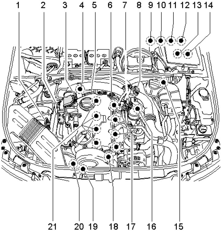
2.2a. 4-cylinder SOHC diesel engine control system parts 1. MAF sensor; 2. EGR valve; 3. Intake manifold flap actuator; 4. ECT sensor; 5. Twin pump; 6. Multi-pin connector; 7. Fuel temperature sensor; 8. Boost pressure sensor with IAT sensor; 9. K/L MIL; 10. Accelerator pedal position sensors; 11. Brake pedal position sensor and brake lights; 12. Clutch pedal position sensor; 13. Holder for 4 relays in the mounting block; 14. ECM; 15. Electrical wiring connectors on the left side of the engine compartment bulkhead; 16. SCR sensor; 17. Glow plugs; 18. SMR sensor; 19. Solenoid valve for regulating the boost pressure; 20. Pump injectors
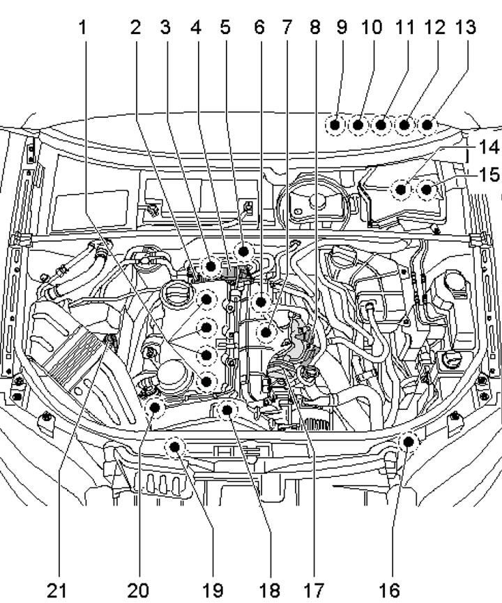
2.2b. 4-cylinder DOHC diesel engine control system parts 1. Pump-injectors and glow plugs; 2. Multi-pin connector; 3. ECT sensor; 4. Twin pump; 5. Fuel pressure sensor; 6. SCR sensor; 7. 3-pin CMP sensor connector; 8. Intake manifold flap actuator; 9. K/L MIL; 10. Accelerator pedal position sensors; 11. Brake pedal position sensor and brake lights; 12. Clutch pedal position sensor; 13. Holder for 3 relays in the mounting block; 14. ECM; 15. Relay and fuse holder on the left side of the gutter; 16. Boost pressure sensor with IAT sensor; 17. EGR valve; 18. SMR sensor; 19. Solenoid valve for regulating the boost pressure; 20. Intake manifold flap valve and EGR radiator switching valve; 21. MAF sensor
(The original article is available on the website: audimanual.ru)