
Withdrawal
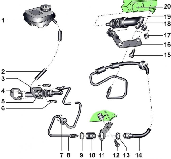
Pic. 8–1. Hydraulic clutch drive: 1 - tank; 2 - fluid supply hose to the clutch master cylinder; 3 - elbow; 4 - gasket; 5 - the main cylinder of the clutch drive; 6 - bolt, 20 Nm; 7 - sealing ring; 8 - tube with couplings, 15 Nm; 9 - washer; 10 - bushing; 11 - bracket; 12 - bolt, 25 Nm; 13 - washer; 14 - tube with couplings, 15 Nm; 15 - bolt; 16 - bracket, 17 - protective cap; 18 - bleed valve, 4.5 Nm; 19 - clutch slave cylinder; 20 - gearbox
Use a clamp to pinch the hose 2 (pic. 8–1) fluid supply to the clutch master cylinder.
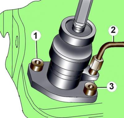
Pic. 8–2. Bolt location (1, 3) fittings and tube connection (2) to the clutch master cylinder
Unscrew the coupling and disconnect the tube from the master cylinder (pic. 8–2).
Unscrew two bolts 1 and 3 securing the clutch master cylinder.
Pull out the master cylinder.
Installation
Installation is carried out in the reverse order of removal, taking into account the following.
When replacing the clutch master cylinder, check that the distance A from the axis of the pusher to the flange of the master cylinder was (114±0,5) mm (pic. 8–3).
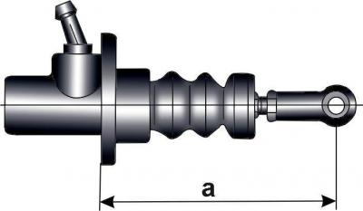
Pic. 8–3. Place for measuring the distance from the axis of the pusher to the flange of the main cylinder: a = (114±0,5) mm
Use a new gasket when installing.
Before screwing onto the thread of the bolt 15 (see fig. 8–1) locking compound D 185 must be applied.
Bleed the air from the hydraulic clutch actuator.
Visitor comments