
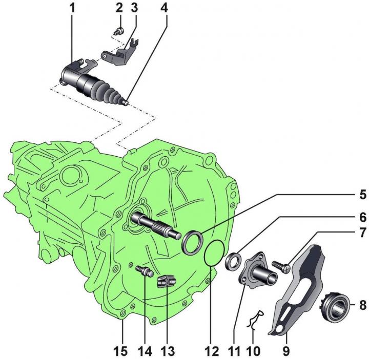
Fig. 8–5. Clutch release mechanism: 1 – clutch slave cylinder; 2 – bolt; 3 – bracket; 4 – pusher; 5 – disc washer; 6 – seal of the gearbox input shaft; 7 – self-locking bolt, 35 Nm; 8 – clutch release bearing; 9 – clutch release lever; 10 – locking spring; 11 – Clutch release sleeve; 12 – sealing ring; 13 – intermediate element; 14 – stud with ball pin, 25 Nm, 15 – gearbox
Before screwing into the thread of bolt 2 (Fig. 8–5), it is necessary to apply D 185 locking compound.
The convex side of washer 5 must be directed towards the guide sleeve.
The sealing ring is installed until it stops.
When installing, it is necessary to use a new bolt 7.
Do not wash the clutch release bearing in solvent, otherwise the grease will be washed out. A bearing that makes noise when rotating must be replaced.
During installation, the working surface of the clutch release lever is lubricated with Z 381 351 TE grease.
The locking spring 10 is attached to the clutch release lever.
When installing, it is necessary to use a new sealing ring 12.
The ball pin is lubricated with molybdenum disulfide based grease.
A lubricant based on molybdenum disulfide is applied to the head of the pusher 4 (see Fig. 8–5).
Before installing the clutch slave cylinder into the gearbox housing, it is necessary to clean the landing area
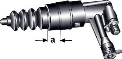
Fig. 8–6. Clutch slave cylinder
a (Fig. 8–6) lubricate with a thin layer of grease.
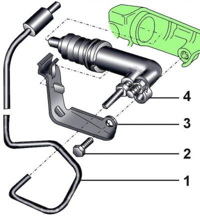
Fig. 8–7. Fastening the clutch slave cylinder: 1 – tube; 2 – bolt; 3– bracket; 4 – working cylinder
Install and secure the tube mounting bracket to the working cylinder (Fig. 8–7).