Repair Chevrolet Repair Toyota Repair Honda Repair AvtoVAZ Repair Mercedes-Benz Repair BMW Repair Opel
Home  |  Contacts  |  Sitemap  |    
English Русский
Български
Беларускі
Український
Српски
Hrvatski
Română
Polski
Slovenský
Magyar
AudiManual.ru


  • AUDI 80
  • AUDI 100
  • AUDI A3
  • AUDI A4
  • AUDI A6
  • AUDI A8
  • AUDI Q
  • OTHER
  • ARTICLES
C4 (1990-1994) C4 (1990-1994, petrol) C3 (1982-1990) C3 (1982-1990, petrol) C3 (1982-1990, diesel)

Clutch release bearing and mechanism — removal, inspection and installation (Audi 100 C3)

  • Home
  • Audi 100
  • C3 (1982-1990, diesel)
  • Transmission
  • Clutch
  • Clutch release bearing and mechanism — removal, inspection and installation
            0
Table of contents: Cable controlled clutch ↓ Hydraulically controlled clutch ↓
1. With the transmission removed from the vehicle, proceed as follows according to type.

Cable controlled clutch


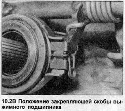
2. The release bearing can be removed by removing the release lever to disengage the forks from the spring clamps, or by removing the brackets on each side of the bearing (photo). The bearing can now be removed from the guide sleeve.

2. The release bearing can be removed by removing the release lever to disengage the forks from the…


2. The release bearing can be removed by removing the release lever to disengage the forks from the…


3. Mark the release lever relative to the shaft, unscrew the clamp bolt and remove the lever.

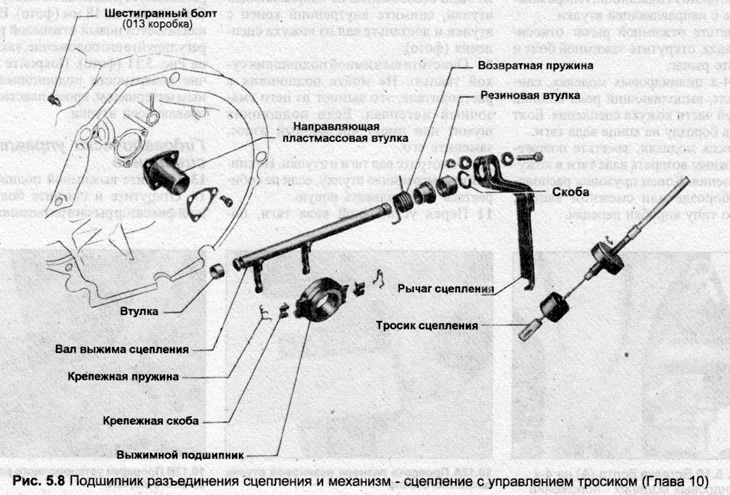
4. On 4-cylinder models, remove the bolt that acts as a key on the rear of the clutch housing. The bolt fits into a groove on the end of the tie rod.

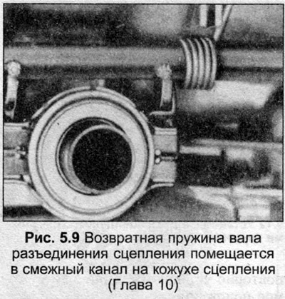
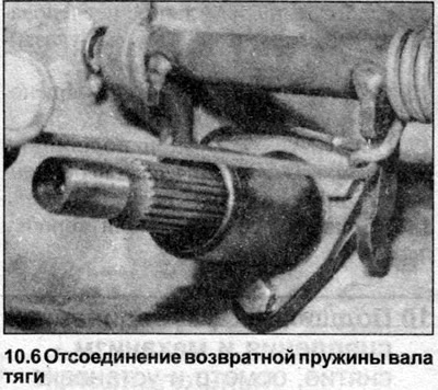
5. On all models, note the position of the traction shaft return spring in the clutch housing. The end of the spring is located in a groove or adjacent channel, according to the type of gearbox.


6. Disconnect the return spring from the traction shaft fork (photo).

6. Disconnect the return spring from the traction shaft fork (photo).


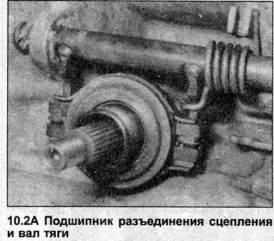
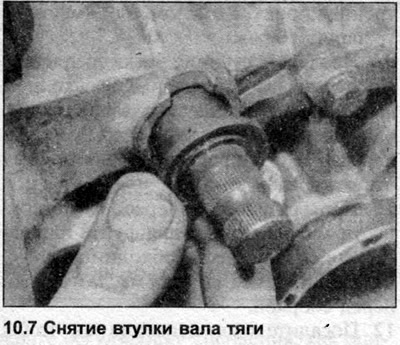
7. Remove the retaining ring from the end of the traction shaft, remove the rubber bushing (where is there) and a flange bushing (photo).

7. Remove the retaining ring from the end of the traction shaft, remove the rubber bushing (where…


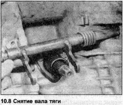
8. Rotate the tie rod shaft so that the fork is free from the guide sleeve, remove the inner end from the sleeve and remove the shaft from the clutch housing (photo).

8. Rotate the tie rod shaft so that the fork is free from the guide sleeve, remove the inner end…


9. Clean the release bearing with a dry cloth. Do not wash the bearing in solvent, as this will wash out the lubricant. If the bearing is noisy or excessively worn, replace it.


10. Inspect the tie rod shaft and bushings. Do not remove the inner bushing unless you are installing a new one.

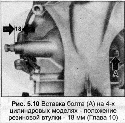
11. Before installing the traction shaft, coat the working surfaces of the bearing with molybdenum grease, check the installation of the return spring on the shaft.

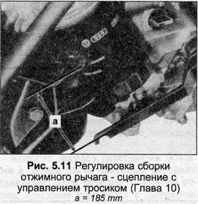
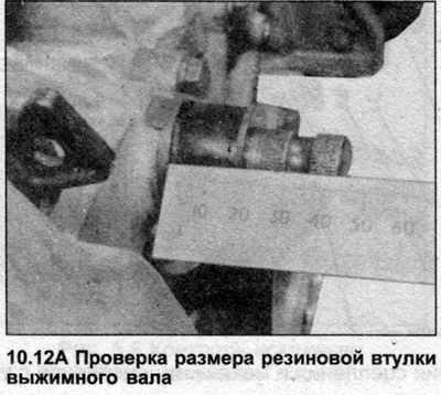
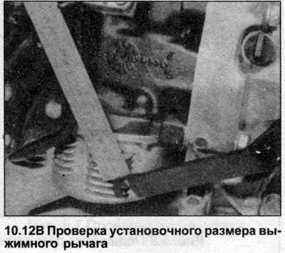
12. Installation is carried out in the reverse order. On 4-cylinder models, the rubber bushing should protrude approximately 18 mm (photo). If a new release lever is installed, adjust its position as shown in Fig. 5.11 (photo). Coat all working surfaces of the bearing with grease, except for the plastic guide bushing.

12. Installation is carried out in the reverse order. On 4-cylinder models, the rubber bushing…


12. Installation is carried out in the reverse order. On 4-cylinder models, the rubber bushing…


12. Installation is carried out in the reverse order. On 4-cylinder models, the rubber bushing…


Hydraulically controlled clutch


13. Remove the release bearing.

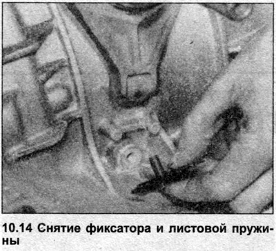
14. Loosen and remove the bolt securing the clutch release lever retainer and leaf spring (photo). Remove the retainer and spring, disconnect the clutch release lever.

14. Loosen and remove the bolt securing the clutch release lever retainer and leaf spring (photo).…


15. Clean the release bearing. Coat the top of the head inside the clutch housing, all working surfaces of the clutch control lever with molybdenum grease, install the lever and release bearing.

15. Clean the release bearing. Coat the top of the head inside the clutch housing, all working…

15. Clean the release bearing. Coat the top of the head inside the clutch housing, all working…


15. Clean the release bearing. Coat the top of the head inside the clutch housing, all working…
The article was checked by auto expert Nikita Rudakov
This article is available at russian, bulgarian, belarusian, ukrainian, serbian, croatian, romanian, polish, slovak, hungarian

Share information:
Previous articles
Audi 100 C3: Clutch
Next articles

Clutch — removal, inspection and installation
Clutch slave cylinder — overhaul
Clutch slave cylinder — removal and installation
Clutch Master Cylinder — Overhaul
Clutch hydraulic system — bleeding


Similar articles on other Audi car models:
Release bearing and lever — removal and installation Audi 80 B3 (1986-1991, petrol)
Removal, installation and checking the clutch Audi A3 Type 8L (1996-2003)
Release bearing and lever — removal, inspection and installation Audi A4 B5 (1994-2001)
Clutch — removal, installation and inspection Audi A6 C5 Allroad (1999-2005)
Clutch release mechanism Audi A8 D2 (1994-2002)
Removal and installation the mechanism and chain for the… Audi Q7 Typ 4L (2005-2015, diesel)
Removal, installation and repair of the clutch release bearing Audi A2 (1999-2005)
Link to this page in different formats


Visitor comments

No comments yet


How much will 20 + 25 =


100(C4, 1990-1994) 
  • General information
  • User manual
  • Power unit
  • Engine repair
  • Ignition system
  • Fuel system (gasoline)
  • Fuel system (diesel)
  • Lubrication system
  • Cooling system
  • Exhaust system
  • Transmission
  • Clutch
  • Car gearbox
  • Drive shafts
  • Chassis
  • Car suspension
  • Steering
  • Wheels and tires
  • Brake system
  • Body
  • Ventilation and heating
  • Body repair
  • Electrical equipment
  • Power devices
  • Lighting and appliances
  • Electrical circuits
 
100(C4, 1990-1994, petrol) 
  • General information
  • Operation and maintenance
  • Power unit
  • Engine repair
  • Exhaust system
  • Cooling system
  • Supply system
  • Air filter
  • Mono-Motronic injection system
  • Digifant injection system
  • KE-III-Jetronic and KE-Motronic
  • MPI and MPFI injection system
  • Transmission
  • Clutch
  • Car gearbox
  • Chassis
  • Suspension and steering
  • Brake system
  • Wheels and tires
  • Body
  • Exterior
  • Interior
  • Electrical equipment
  • Fuses and relays
  • Power devices
  • Ignition system
  • Lighting and signaling
  • Equipment and devices
  • Electrical circuits
 
100(C3, 1982-1990) 
  • General information
  • User manual
  • Maintenance
  • Specifications
  • Power unit
  • Engines 4-cylinder
  • Engines 5-cylinder
  • Diesel engine
  • Cooling system
  • Power system (carburetor)
  • Power system (injector)
  • Fuel system (diesel)
  • Transistor ignition system
  • Electronic ignition system
  • Transmission
  • Clutch
  • 4 speed gearbox 014
  • 5 speed gearbox 013 and 093
  • 5 speed gearbox 016 and 012
  • Shift mechanism KP 016
  • Automatic transmission
  • Front wheel drive
  • Chassis
  • Front suspension
  • Rear suspension
  • Steering
  • Brake system
  • Body
  • Body elements
  • Electrical equipment
  • Lighting and appliances
  • Power devices
  • Electrical circuits
 
100(C3, 1982-1990, petrol) 
  • General information
  • Maintenance and operation
  • 4 cylinder engine
  • Engine repair
  • Cooling and lubrication system
  • Supply system
  • Ignition system
  • 5 cylinder engine
  • Engine repair
  • Cooling and lubrication system
  • Supply system
  • Ignition system
  • Transmission
  • Clutch and drive shafts
  • 4 speed gearbox 014
  • 5 speed gearbox 013 and 093
  • 5 speed gearbox 016 and 012
  • Automatic gearbox
  • Chassis
  • Steering
  • Front suspension
  • Rear suspension
  • Brake system
  • Body
  • Body elements
  • Doors, locks and windows
  • Body repair
  • Electrical equipment
  • Equipment and devices
  • Power devices
  • Electrical circuits
 
100(C3, 1982-1990, diesel) 
  • General information
  • User manual
  • Maintenance
  • Troubleshooting
  • Power unit
  • Engine in a car
  • Engine removed
  • Cooling system
  • Fuel system
  • Exhaust system
  • Starting and charging
  • Preheating
  • Transmission
  • Clutch
  • Mechanical gearbox
  • Automatic gearbox
  • Drive shafts
  • Chassis
  • Brake system
  • Suspension
  • Steering
  • Body
  • Exterior
  • Interior
  • Electrical equipment
  • Equipment and devices
  • Electrical circuits
 
AudiManual.ru © 2017-2026 · Mobile version · Feedback · Sitemap: EN BG BY UA RS HR RO PL SK HU · Site search · News and articles
80 B2 · 80 B3 petrol · 80 B3 · 80 B4 · 100 C3 diesel · 100 C3 petrol · 100 C3 · 100 C4 petrol · 100 C4 · A3 Type 8L · A4 B5 petrol · A4 B5 · A4 B6 petrol · A4 B6 · A4 B7 · A4 B8 · A6 C4 · A6 C5 · A6 C5 Allroad · A8 D2 · Q5 Type 8R · Q7 Typ 4L · Audi A2 ·
This site uses cookies 🍪. Click the button to accept this fact.