
Note: Refer to the warning at the beginning paragraph 2 about the harmfulness of hydraulic fluid.
Removal
1. The clutch master cylinder is located in the passenger compartment on the brake and clutch pedal bracket. Hydraulic fluid is supplied to it from the brake fluid reserve tank.
Right hand drive models
2. Before starting the procedure, lay a rag on the carpets of the car interior to avoid staining them with hydraulic fluid.
3. Under the hood, clamp the brake fluid hose from the reserve tank to the clutch master cylinder.
4. Pull the hose off the clutch master cylinder on the firewall.
5. Loosen the union nut and disconnect the hydraulic tube from the master cylinder. Plug or tape the tube to prevent dirt from getting into the system and fluid from spilling.
6. Working in the passenger compartment, remove the storage box under the steering wheel as described in chapter 11. Open the lid, unscrew the fastening screw and pull the box out of the clamps on the front panel. This will give you access to the pedal bracket.
7. If equipped, disconnect the wiring and pull out the sensor/switch from the top of the clutch pedal.
8. Disconnect the master cylinder rod from the pedal by pulling the retainer.
9. Unscrew the mounting bolts with a hex key and remove the master cylinder from the pedal bracket. Note that the rubber seal should remain on the flange of the master cylinder.
Left hand drive models
10. Remove the engine ignition control unit from the left side of the engine shield as described in paragraphs 4 or 5 chapter 4A. To do this on early models, remove the cover from the electronic box by inserting the head through the hole in the cover panel in front of the windshield. Later models do not have holes in the panel and the panel will have to be removed to get to the rear bolt.
11. If provided, remove the additional relay block and additional fuse block.
12. Disconnect the wiring connector and pull the wiring out through the window in the electronic box. Unscrew the mounting nuts at the rear of the box and, having unhooked the box from the guide lug, remove it from the engine shield.
13. Before starting the procedure, lay rags on the carpets of the car interior to avoid staining them with spilled hydraulic fluid.
14. Carefully clamp the hose that leads from the brake reservoir to the clutch master cylinder.
15. Pull the hose off the clutch master cylinder on the firewall.
16. On early models, unscrew the union nut and disconnect the hydraulic pipe from the clutch master cylinder. The union nut is partially covered by the brake booster. On later models, use a screwdriver to unhook the retainer and remove the hydraulic pipe from the master cylinder. Plug the pipe or tape it to prevent dirt from getting into the system and brake fluid from leaking out.
17. Using a Torx head, unscrew the bolts securing the master brake cylinder.
18. Working inside the car, remove the storage box under the steering column to access the pedal bracket as described in chapter 11. Open the lid, unscrew the fastening screws and pull the box off the front panel clamps.
19. Use a screwdriver to release the master cylinder rod retainer by turning it upward and pulling it off the pedal. Pull the pedal upward to disconnect it from the rod.
20. Using a hex key, unscrew the clutch master cylinder mounting bolts and the upper pedal bracket bolt, pull the bracket with the master cylinder out a little and remove the master cylinder. Make sure that the rubber seal remains on the master cylinder flange.
Repair
21. Audi does not produce repair kits, but other factories do.
22. Before starting repairs, clean the outer surfaces.
23. Remove the rubber boot and remove the stem. If necessary, loosen the lock nut, unscrew the fork with the lock nut and remove the stem from the rubber seal. Note the distance between the center of the stem eye and the mounting flange to reinstall it correctly.
24. Remove the retaining ring from the cylinder bore, remove the washer, piston and spring, remembering that the smaller end of the spring contacts the piston.
25. Clean the components and check for damage. If the piston and cylinder are excessively worn or corroded, replace the entire cylinder. If the piston and cylinder are in good condition, remove all rubber seals and replace them with new ones.
26. Soak the new seals in hydraulic fluid and install them on the piston using only your fingers. The sealing edges should face the spring.
27. Insert the spring into the cylinder, immerse the piston in hydraulic fluid and carefully insert the piston.
28. Install the washer, then install the snap ring into the groove.
29. Apply grease to the tip of the rod, insert it into the piston and install the rubber boot.
30. Tighten the lock nut and fork and adjust the distance between the center of the eye and the surface of the mounting flange facing the engine shield. On right-hand drive models, it should be 139±0.5 mm and on left-hand drive models, 165±0.5 mm.
Installation
31. Installation - reverse procedure. Tighten the threaded connections to the prescribed torques. Apply grease to the fork eye before installation. Bleed the clutch system as described in paragraph 2. On left-hand drive models, before installing the electronic gearbox, check the condition of the engine shield gasket and replace it if necessary. Finally, check the installation of the clutch pedal sensor/switch as follows. When the pedal is released, the gap between the sensor plunger and the main body should be no more than 0.5 mm. The gap between the pedal bracket and the protrusions on the sensor body should also be no more than 0.5 mm. The gap is adjusted by turning the sensor (fig. 44.31).
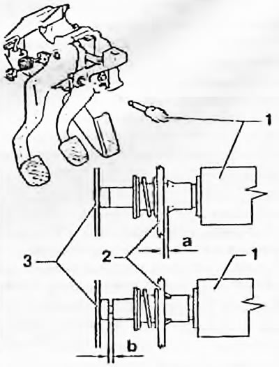
Fig. 4.31. Adjusting the clutch drop sensor/switch:
1. Sensor
2. Mounting bracket
3. Clutch pedal
a and b - 0.5 mm