Repair Chevrolet Repair Toyota Repair Honda Repair AvtoVAZ Repair Mercedes-Benz Repair BMW Repair Opel
Home  |  Contacts  |  Sitemap  |    
English Русский
Български
Беларускі
Український
Српски
Hrvatski
Română
Polski
Slovenský
Magyar
AudiManual.ru


  • AUDI 80
  • AUDI 100
  • AUDI A3
  • AUDI A4
  • AUDI A6
  • AUDI A8
  • AUDI Q
  • OTHER
  • ARTICLES
B8 (2007-2015) B7 (2004-2008) B6 (2000-2006) B6 (2000-2006, petrol) B5 (1994-2001) B5 (1994-2001, petrol)

Clutch assembly — removal, inspection and installation (Audi A4 B5)

  • Home
  • Audi A4
  • B5 (1994-2001)
  • Transmission
  • Clutch
  • Clutch assembly — removal, inspection and installation
            0
Table of contents: Removal ↓ Examination ↓ Installation ↓
Warning! Dust, as a product of friction lining wear, may contain asbestos, which is hazardous to health. DO NOT blow it off with compressed air or inhale it. DO NOT use gasoline or gasoline-based solvents to remove dust. Use a special clutch cleaning fluid or methyl alcohol to wash the dust into a container. After wiping the clutch with a rag, put it together with the wear products washed off with a special fluid in a container, marking it.


Removal


1. Remove the gearbox as described in chapter 7A.

2. Before removing the discs, mark the position of the clutch basket relative to the flywheel with a marker or chalk.

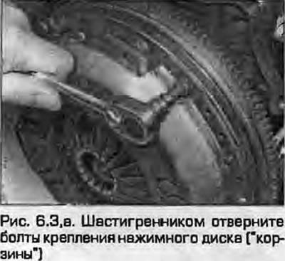
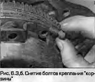
3 Working in a diagonal sequence, gradually loosen the basket-to-flywheel mounting bolts with a hex key, loosening them half a turn at a time until the spring weakens and the bolts can be loosened by hand. After loosening the bolts two or three turns, check to see if the basket is stuck on the guide pins; separate it from the flywheel with a screwdriver if necessary. After this, unscrew the bolts and remove the basket.


Clutch assembly — removal, inspection and installation

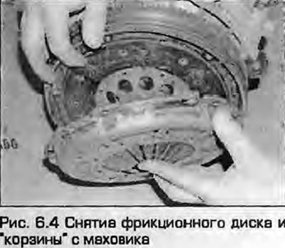
4. After removing the basket, remove the friction disc, remembering which side to install it back on.


4. After removing the basket, remove the friction disc, remembering which side to install it back…


Examination


5. Before cleaning the clutch, read the warning at the beginning of this chapter. Remove dust using a clean cloth in a well-ventilated area.

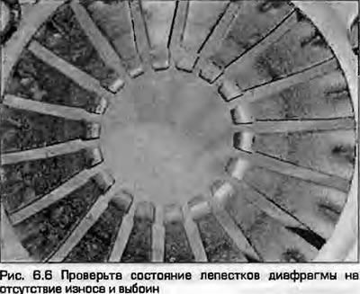
6. Check the wear of the diaphragm spring petals (Fig. 6.6). If they are worn down to half, the basket must be replaced.

6. Check the wear of the diaphragm spring petals (Fig. 6.6). If they are worn down to half, the…


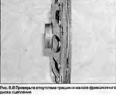
7. Check the contact surfaces of the clutch friction disc for signs of wear, damage and contamination. If the friction material has cracks, burnt areas, pits, dirt, oil (shiny black spots), worn, replace the friction disc.

8. If the friction linings are intact, check the disc hub (Fig. 6.8). The rivets should not be damaged, the torsion springs of the torsional vibration damper should not be broken or loose in their sockets, the splines should not be worn or damaged. If defects are found, replace the disc.


8. If the friction linings are intact, check the disc hub (Fig. 6.8). The rivets should not be…


9. Check the contact surfaces of the flywheel and pressure plate. They must be absolutely flat, smooth, without burrs or cracks, without signs of overheating. If defects are found that cannot be eliminated with sandpaper, it may make sense to grind the flywheel, otherwise replace the part.

10. Before assembly, clean all parts from dirt and dust. Apply a thin layer of high-temperature grease to the splines of the friction disk hub. If a new clutch pressure plate is installed, it can be coated with preservative grease. Grease can only be removed from the contact surface of the disk; removing it from other parts reduces the service life of the "basket".

Installation


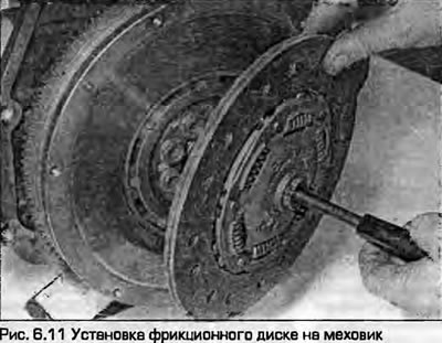
11. Install the TEK friction disc so that the protruding part of its hub faces outward from the flywheel. The disc should also be marked by the manufacturer indicating which side to install it on. If necessary, use a drift (Fig. 6.11).

11. Install the TEK friction disc so that the protruding part of its hub faces outward from the…


12. Install the clutch basket onto the flywheel using the guide pins, aligning the marks made during removal (if the old basket is installed).


12. Install the clutch basket onto the flywheel using the guide pins, aligning the marks made…


13. Screw in the basket mounting bolts, tightening them only by hand so that the friction disc can be moved.

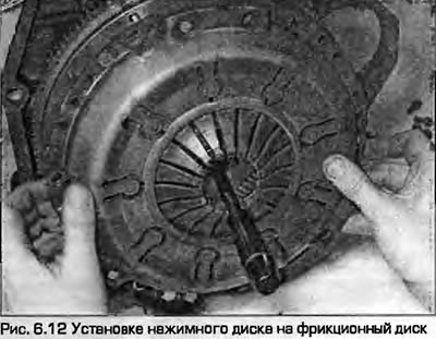
14. Now you need to center the friction disk so that when installing the gearbox, its primary shaft passes through the splines in the disk and ends up in the center of the crankshaft. You can center the friction disk using a screwdriver by inserting it into the central hole of the disk and crankshaft and moving the disk until the centers of the holes are aligned. This task can be made easier by using a mandrel in the shape of the primary shaft of the gearbox, which can be purchased from a dealer or ordered to be made in a lathe shop. Good results can be obtained by winding the appropriate amount of electrical tape on a suitable piece of round stick or a long bolt that fits tightly into the hole of the crankshaft.

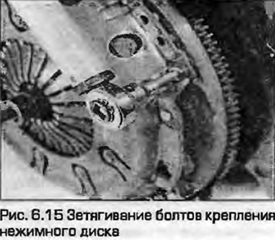
15. After centering the friction disc, gradually tighten the pressure plate mounting bolts in a diagonal sequence to the specified torque. After tightening the bolts, remove the centering mandrel (Fig. 6.15).

15. After centering the friction disc, gradually tighten the pressure plate mounting bolts in a…


16. Check the smoothness of the release bearing and, if necessary, replace it as described in paragraph 7.


17. Install the gearbox as described in chapter 7A.

(A link to the original source is available on the website: AUDImanual.ru)
The article was checked by auto expert Timur Bazhenov
This article is available at russian, bulgarian, belarusian, ukrainian, serbian, croatian, romanian, polish, slovak, hungarian

Share information:
Previous articles
Audi A4 B5: Clutch
Next articles

Clutch slave cylinder — removal, repair and installation
Clutch Master Cylinder — Removal, Repair and Installation
Clutch pedal — removal and installation
Hydraulic clutch drive — bleeding
Release bearing and lever — removal, inspection and installation


Similar articles on other Audi car models:
Clutch — removal, inspection and installation Audi 80 B3 (1986-1991, petrol)
Clutch — removal, inspection and installation Audi 100 C3 (1982-1990, diesel)
Removal, installation and checking the clutch Audi A3 Type 8L (1996-2003)
Clutch — removal, installation and inspection Audi A6 C5 Allroad (1999-2005)
Removal and installation the engine Audi A8 D2 (1994-2002)
Removal and installation the hub assembly Audi Q7 Typ 4L (2005-2015, diesel)
Removal and installation the clutch Audi A2 (1999-2005)
Link to this page in different formats


Visitor comments

No comments yet


How much will 10 + 33 =


A4(B8, 2007-2015) 
  • General information
  • Operating instructions
  • Power unit
  • Petrol engines 1.8 l
  • Petrol engines 1.8/2.0 l
  • Petrol engines 3.0 l
  • Petrol engines 3.2 l
  • Fuel system (petrol)
  • Diesel engines 2.0 l (CA*)
  • Diesel engines 2.0 l (CJCB)
  • Diesel engines 2.7/3.0 l
  • Diesel engines 3.0 l
  • Fuel system (diesel)
  • Transmission
  • Manual gearbox 0B1
  • Manual gearbox 0B2
  • Manual gearbox 0B3
  • Manual gearbox 0B4
  • Automatic transmission 0B5
  • Automatic transmission 0B6
  • Automatic transmission 0AW
  • All-wheel drive system
  • Chassis
  • Front suspension
  • Rear suspension
  • Brake system
  • Steering system
  • Body
  • Exterior
  • Interior
  • Seats
  • Doors, locks and windows
  • Security system
  • Heating and air conditioning
  • Electrical equipment
  • Audio system
  • Power devices
  • Equipment and devices
  • Lighting and lamps
  • Electrical circuits
 
A4(B7, 2004-2008) 
  • General information
  • Introduction to manual
  • Troubleshooting
  • Operating instructions
  • Maintenance
  • Power unit
  • Petrol engines 2.0 (ALT)
  • Petrol engines 2.0 (TFSI)
  • Petrol engines 1.8 (MPI)
  • Diesel engines
  • Cooling system
  • Air conditioner
  • Fuel and exhaust system
  • Ignition system
  • Starting and charging
  • Transmission
  • Clutch
  • Manual gearbox
  • Automatic gearbox
  • Drive shafts
  • Chassis
  • Brake system
  • Front suspension
  • Rear suspension
  • Steering
  • Body
  • Exterior
  • Interior
  • Electrical equipment
  • Equipment and devices
  • Lighting and signaling
  • Windscreen wipers and washers
  • Electrical diagrams
  • Electrical diagrams (since 2007)
 
A4(B6, 2000-2006) 
  • General information
  • Vehicle Description
  • User manual
  • Maintenance
  • Power unit
  • Gasoline engine
  • Diesel engine
  • Lubrication system
  • Cooling system
  • Supply system
  • Injection system
  • Exhaust system
  • Ignition and control
  • Transmission
  • Gear box
  • Clutch and drive shafts
  • Chassis
  • Brake system
  • Car suspension
  • Steering
  • Body
  • Heating and ventilation
  • Exterior (external elements)
  • Interior (internal elements)
  • Electrical equipment
  • Power devices
  • Lighting and appliances
  • Electrical circuits
 
A4(B6, 2000-2006, petrol) 
  • General information
  • Introduction to the guide
  • Car care
  • Power unit
  • Engine repair
  • Lubrication system
  • Cooling system
  • Injection and control system
  • Ignition system
  • Power and exhaust system
  • Transmission
  • Clutch and drive shafts
  • Car gearbox
  • Chassis
  • Suspension and wheels
  • Steering
  • Brake system
  • Body
  • Interior
  • Exterior
  • Electrical equipment
  • Equipment and devices
  • Lighting and signaling
  • Power devices
  • Electrical circuits
 
A4(B5, 1994-2001) 
  • General information
  • Introduction to the guide
  • Car care
  • Maintenance (gasoline)
  • Maintenance (diesel)
  • Power unit
  • Gasoline engines
  • Diesel engines
  • Engine overhaul
  • Cooling system
  • Fuel injection (gasoline)
  • Fuel system (diesel)
  • Exhaust system
  • Ignition system
  • Transmission
  • Clutch
  • Mechanical gearbox
  • Automatic gearbox
  • Drive shafts
  • Chassis
  • Brake system
  • Car suspension
  • Steering
  • Body
  • Exterior
  • Interior
  • Doors, locks and windows
  • Heating and ventilation
  • Electrical equipment
  • Power devices
  • Equipment and devices
  • Electrical circuits
 
A4(B5, 1994-2001, petrol) 
  • General information
  • Vehicle description
  • Maintenance
  • Power unit
  • Engine repair
  • Turbocharging
  • Exhaust system
  • Cooling system
  • Ignition system
  • Fuel system
  • Motronic injection system
  • MPI and MPFI injection system
  • Transmission
  • Clutch
  • Gearbox and shafts
  • Chassis
  • Steering
  • Car suspension
  • Brake system
  • Wheels and tires
  • Body
  • Heating and ventilation
  • Body parts
  • Electrical equipment
  • Fuses and relays
  • Power devices
  • Lighting and lamps
  • Tools and devices
  • Electrical circuits
 
AudiManual.ru © 2017-2026 · Mobile version · Feedback · Sitemap: EN BG BY UA RS HR RO PL SK HU · Site search · News and articles
80 B2 · 80 B3 petrol · 80 B3 · 80 B4 · 100 C3 diesel · 100 C3 petrol · 100 C3 · 100 C4 petrol · 100 C4 · A3 Type 8L · A4 B5 petrol · A4 B5 · A4 B6 petrol · A4 B6 · A4 B7 · A4 B8 · A6 C4 · A6 C5 · A6 C5 Allroad · A8 D2 · Q5 Type 8R · Q7 Typ 4L · Audi A2 ·
This site uses cookies 🍪. Click the button to accept this fact.