
Table of contents: Removal ↓ Installation ↓
Removal
1. Select a level, solid area and position the vehicle so that there is enough room to work. Apply the handbrake and place chocks under the rear wheels.
2. Raise the front of the vehicle and install safety stands. Remove the lower engine cover from under the vehicle.
3. Disconnect the ground cable from the battery as described in chapter 5A.
4. Remove the air filter as described in the chapter 4A or 4B.
5. On turbocharged models, unscrew the screws and remove the coolant expansion tank, moving it to the side. Do not disconnect the hoses from the tank. Disconnect the oxygen sensor wiring on the engine shield.
6. As described in Chapter 5B, disconnect the exhaust pipe and catalytic converter. Be careful not to bend the flexible section of the exhaust pipe excessively.
7. Unscrew the gearbox mounting bolts to the engine, accessible from above (from the engine compartment).
8. In the front part of the engine compartment, at the bottom, remove the lower protective casing mounting bracket.
9. Using a hex key, unscrew the bolts securing the heat shields below the inner hinge of the right shaft.
10. Support the gearbox with a trolley jack, remove the right gearbox support together with the rubber bushing.
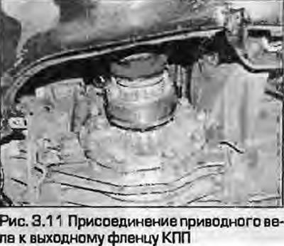
11. As described in Chapter 8, disconnect the drive shafts from the gearbox flanges (Fig. 3.11). Place the shafts on the suspension rods.
12. Disconnect the wiring from the speedometer sensor on the gearbox.
13. Disconnect the wiring from the reverse light switch on the gearbox.
14. Disconnect the wiring from the gearbox housing and the gearbox mounting bolts to the engine.
15. Remove the starter as described in chapter 5A. You don't have to disconnect the wiring from the starter, just move the starter to the side and tie it up.
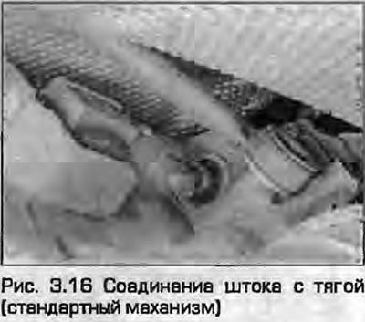
16. Loosen the bolt and disconnect the shift rod from the gearbox (Fig. 3.16).
17. On short-throw shift models, remove the bolt and disconnect the distance rod.
18. Make sure the gearbox support is secure and unscrew the remaining bolts securing the gearbox to the engine.
19. Unscrew the bolt securing the left gearbox support to the rubber cushion.
20. With the help of an assistant, remove the gearbox from the guide bushings on the engine, making sure that the gearbox input shaft does not rest on the clutch basket. Lower the gearbox so that you can get to the clutch slave cylinder. Make sure that the drive shafts are moved away from the gearbox.
Warning: Make sure the transmission is securely supported. Keep the transmission level until the input shaft disengages from the clutch.
21. Remove the slave cylinder from the gearbox and move it to the side, tying it up.
Note: Do not press the clutch pedal with the slave cylinder removed.
22. Lower the gearbox.
Installation
23. Before installation, make sure that the guide bushings are correctly installed in the cylinder block. Check the installation of the lower starter mounting bolt - after installing the gearbox, it will no longer be inserted.
24. Installation - reverse procedure. Please note the following:
- a) Check the condition of the rubber mounts and replace them if necessary.
- b) Apply high temperature grease to the splines of the gearbox input shaft.
- c) Tighten all nuts and bolts to the specified torque.
- d) In conclusion (see paragraph 2), check the adjustment of the switching mechanism.