
Table of contents: Right hand drive models ↓ Left hand drive models ↓
Right hand drive models
Removal
1. Remove the storage box/panels under the steering column as described in chapter 11. Open the lid, unscrew the mounting screws and pull the box off the clips on the front panel. This will give you access to the pedal bracket.
2. If equipped with a sensor/switch, disconnect the wiring and remove the switch above the pedal.
3. Use a screwdriver to loosen the retainer and release the clutch master cylinder rod from the pedal.
4. Loosen the axle bolt to the left of the pedal axle, remove the lever and lower the pedal from the bracket, simultaneously releasing it from the servo spring. Remember the position of the bushing, bearings, washers and caps so that everything can be reassembled correctly later.
5. If necessary, the bearings can be replaced separately from the pedal (Fig. 3.5).
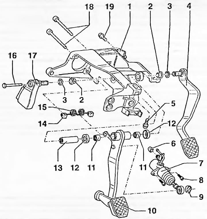
Fig. 3.5. Pedal assembly components on right-hand drive models: 1. Mounting bracket; 2. Thrust bushing; 3. Washer; 4. Brake pedal; 5. Bracket mounting bolt; 6. Compaction; 7. Clutch master cylinder; 8. Bolt; 9. Retainer; 10. Clutch pedal; 11. Needle bearing; 12. Cap; 13. Main bushing; 14. Bearing; 15. Servo spring; 16. Bolt; 17. Brake lever; 18. Bolts for mounting the servo booster and master brake cylinder; 19. Bracket mounting bolt
Installation
6. Installation - reverse procedure, first lubricate the bearings and bushing. Make sure the pedal is installed correctly - see chapter 9.
Left hand drive models
Removal
7. Remove the storage box/panels under the steering column as described in chapter 11. Open the lid, unscrew the mounting screws and pull the box off the clips on the front panel. This will give you access to the pedal bracket.
8. If equipped with a sensor/switch, disconnect the wiring and remove the switch above the pedal.
9. Use a screwdriver to remove the pin retainer by turning it upwards and pulling it off the pedal. Pull the pedal upwards to release it from the rod (Fig. 3.9).
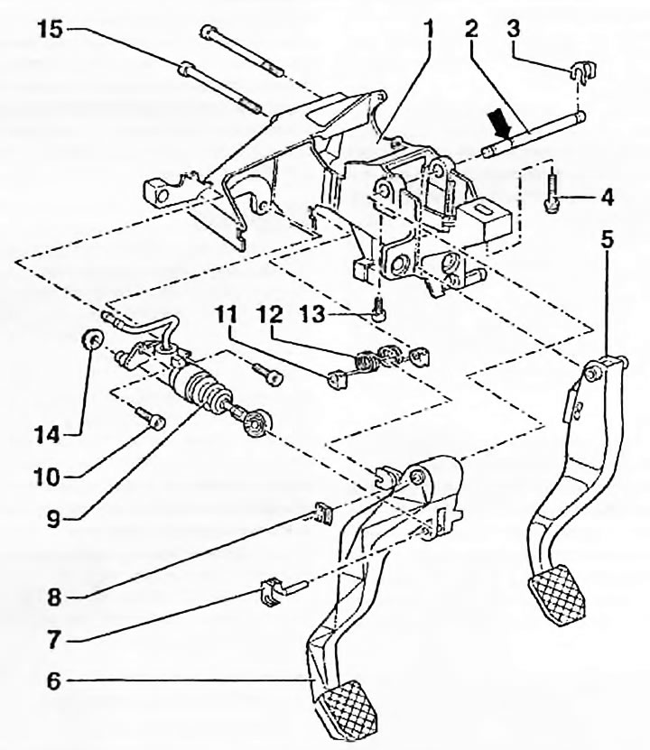
Fig. 3.9. Pedal assembly components on left-hand drive models: 1. Mounting bracket; 2. Axis; 3. Retainer; 4. Bracket mounting bolt; 5. Brake pedal; 6. Clutch pedal; 7. Pusher; 8. Retainer; 9. Clutch master cylinder; 10. Bolt; 11. Servo spring retainers; 12. Servo spring; 13. Axle mounting bolt; 14. Compaction; 15. Bolts for fastening the master brake cylinder and servo booster
10. Remove the pedal retainer from the groove on the left side of the axle.
11. Loosen the axle mounting bolt and push the axle to the right so that the pedal can be removed from the bracket.
12. Remove the servo spring from the slots in the pedal bracket.
Installation
13. Installation - reverse procedure, do not tighten the axle mounting bolt until the axle retainer is installed.