
Removal
1. Remove the gearbox, see the relevant chapter.
2. Mark the position of the pressure plate on the flywheel with a marker or paint.
3. Lock the flywheel with a large screwdriver or punch, inserting it into the toothed ring of the flywheel to keep it from turning when unscrewing the bolts that secure the pressure plate to it. In workshops, a special AUDI-3067 shoe is used for this purpose, which is attached to the toothed ring of the flywheel.
Attention! To center the driven clutch disc when installing the clutch disc, use the AUDI-3176 roller or the non-working primary shaft.
4. Loosen the pressure plate bolts in stages by one to one and a half turns, acting in a crisscross pattern, until the bolts can be unscrewed by hand.
Caution! If you unscrew the bolts completely at once, you may damage the diaphragm spring.
5. Remove the pressure and driven disks.
Caution: When performing this operation, do not drop the discs, otherwise jerking and difficulties with separating the clutch may occur after assembly.
6. Wipe the release bearing. The bearing cannot be washed.
7. Wipe the flywheel with a rag.
Examination
8. Check the pressure plate for cracks, burnout and ribbing.
9. Check the condition of the segments (see arrows in the illustration) diaphragm spring. Wear of segments up to half their thickness is allowed.
10. Check the fastening of the diaphragm spring segments and make sure there are no cracks, the strength of the rivets and their fit. Replace any damaged or loose rivets on the disc.
11. Check the bearing surface of the pressure plate for cracks, burn marks and wear. Disks with an inward deflection of up to 0.2 mm can still be installed. Check using a ruler and a measuring template.
12. Check the condition of the flywheel. Make sure there are no signs of burnout or ribbing.
13. Replace clutch discs with oily surfaces or mechanical damage.
14. Check the thickness of the clutch disc friction lining with a caliper and make sure there are no cracks in the lining.
The clutch disc can be checked for runout in the workshop. The lateral runout of the driven disc should not exceed 0.8 mm or 2.5 mm, if counted from the outer edge. Attention! This check is necessary only if the previous driven disc is to be installed, and the clutch was poorly disengaged before its removal. If necessary, the disc can be carefully straightened.
15. Check the movement of the release bearing without removing it. The bearing should rotate easily, otherwise replace it. When driving, a faulty bearing manifests itself as noise when pressing the clutch pedal. In this case, the bearing must be replaced.
Attention! A release bearing with a plastic ring may be installed. When removing the gearbox, this plastic ring may separate. In this case, the bearing does not need to be replaced. Before installing* the gearbox, lubricate the separated ring with AMV 195KD101 glue and glue it to the outer ring. In this case, the three protrusions on the plastic ring (see arrows in illustration 2.15) should fit into the grooves on the outer ring. If the plastic ring of the release bearing has worn more than 0.5 mm, the release bearing should be replaced.
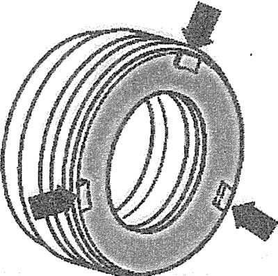
2.15. In this case, three protrusions on the plastic ring (see arrows), should fit into the grooves on the outer ring
Installation
Attention! When installing new pressure and driven clutch discs, follow the engine letter designation and its series to avoid installing incompatible parts. To do this, be sure to check in the spare parts catalog whether the available pressure plate and driven clutch disc are suitable for this engine.
If the old clutch parts are to be installed, their condition should be checked first.
Attention! If the previous driven disk has been burnt due to overloads, then to avoid the appearance of an unpleasant odor in the future, before installing the clutch, you should thoroughly clean the clutch disks, as well as the side of the flywheel facing the gearbox, and the engine parts near the gearbox.
16. Remove the anti-corrosion grease before installing the new pressure plate only from its active surface. Do not remove the grease from other places under any circumstances, otherwise the service life of the clutch will be significantly reduced.
17. Check the reliability of the fit of the flywheel centering pins.
18. Clean off any corrosion and apply a thin coat of molybdenum grease to the splines of the driven disc hub and to the gear ring of the transmission input shaft. Then move the driven clutch disc back and forth on the input shaft until the driven disc hub moves easily on the shaft. Be sure to remove any excess grease.
19 Install the clutch slave disc, making sure that the springs of the torsional vibration damper are facing the pressure plate. The friction lining should be in contact with the flywheel. Some discs have the inscription "Getriebeseite" (the side that should face the gearbox).
20. Center the position of the driven disk on the pressure plate using a suitable shaft, such as AUDI-3176 or HAZET- 2174. If the driven disk is not installed in the center of the pressure plate, it will be impossible to start and install the primary shaft of the gearbox later. As an auxiliary means for centering, you can use the non-working primary shaft of the gearbox.
21. Install the pressure plate onto the corresponding mounting pins on the flywheel.
Caution! The pressure plate must fit completely against the flywheel, without any skewing. Do not allow the pressure plate to skewer, as this will damage the mounting pins and centering holes. Only after centering the disk, insert the mounting bolts. Never tighten the disk with bolts, as this will damage the centering pins.
Caution! When installing a new driven clutch disc with the same pressure plate with an adjusting ring, this ring should be moved back to the stop. Otherwise, the pressure plate will act with reduced force, which will cause accelerated wear of the clutch.
If the driven disk has not been changed, then there is no need to move the adjusting ring back.
22. Insert the pressure plate mounting bolts A into the holes and screw them in about 1/3 of a turn. Screw the nuts B onto the bolts and tighten them only slightly (see illustration).
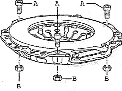
2.22. Insert the pressure plate mounting bolts A into the holes, screw them in about ⅓ of a turn and screw on the nuts
23. Place the pressure plate on the press so that only the bolt heads are in contact with the press plate (see arrows in the illustration), and insert a centering roller, for example 3062, into the disk hole.
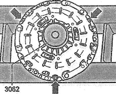
2.23 Place the pressure plate on the press so that only the bolt heads are in contact with the press plate (see arrows), and insert the centering roller into the disk hole
Attention! When performing the following actions, do not perform them by "force". Otherwise, the forks of the adjusting ring will be broken.
24. Press the centering roller and disk with a press until the adjusting ring starts moving and at this point use two screwdrivers to move the ring in the direction of the arrows in the illustration until it stops.
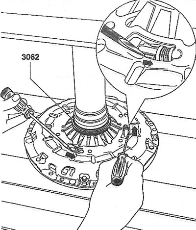
2.24. Move the adjustment ring in the direction of the arrows in the illustration until it stops
25. Hold the adjustment ring in this position and slowly release the press pressure on the disc so that the ring does not move.
26. Insert the pressure plate mounting bolts and tighten them by hand, then turn them in a crisscross pattern by 1-1½ turns until the pressure plate mounting bolts are tightened to the required torque. The tightening torque for the bolts is 25 Nm. The pressure plate must not be tilted, otherwise the dowel pins and the holes for the centering pins will be damaged
27. Remove the driven disk centering tool.
28. Install the gearbox.