



Table of contents: Automatically adjustable rear wheel… ↓ Removal and installation of rear.… ↓ Replacement rear. brake calipers ↓ Removal and installation rear… ↓ Removal and installation rear… ↓ Replacing rear brakes. disks ↓
Automatically adjustable rear wheel brakes
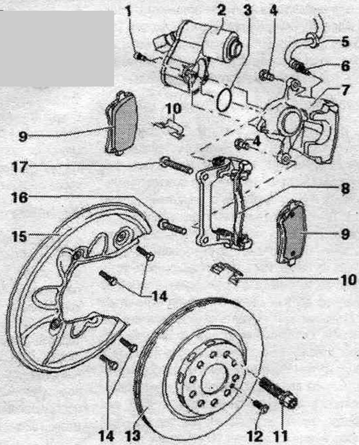
1. Self-locking bolt: 12 Nm.
2. Execution electric motor el. mechan. parking brakes.
3. Sealing ring: must be replaced.
4. Self-locking bolt: 35 Nm; must be replaced; when removing and installing, it is necessary to hold the guide pins from turning.
5. Spacer.
6. Brake hose: to brake caliper, 20 Nm; to replace brakes. there is no need to unscrew the brake pads. pipeline; ensure that the locking spouts are correctly installed in the bracket grooves; secure the hose, preventing it from twisting.
7. Brake caliper: for replacing brakes. unscrew the brake pads. no hose required; it is possible to install a bracket-holder assembled with a brake. support.
8. Bracket with guides and seal. cuffs: supplied in grease, assembled with guides as a single spare part; in case of damage to the seal. install a repair kit on the cuffs or guides; when installing the guides, use the supplied tube of grease; it is possible to install a bracket-holder assembled with a brake. support.
9. Brake pads: Replace all pads for the corresponding axle; it is possible to install a bracket-holder assembled with a brake. caliper. The brake pads must be positioned between both retaining tabs of the bracket to ensure clearance between the disc and the pad.
10. Brake pad holder: always replaced when changing brake pads.
11. Wheel bolts.
12. Bolt: 5 Nm.
13. Brake disc: Replace all pads for the corresponding axle.
14. Hexagon head bolts: 10 Nm.
15. Brake shield.
16. Bolt: 100 Nm and turn further by 90°; replace.
17. Bolts: 100 Nm and tighten by 90°; replace.
Removal and installation of rear. brake caliper with bracket
With the ignition off, connect the VAS 5051 B or VAS 5052 tester to the 16-pin diagnostic connector of the vehicle. Turn on the ignition. Turn off the parking brake. brake. Check coding and adjust if necessary. Interrogate the fault memory, eliminate detected faults, erase errors from the fault memory. Select function "053 - Parking brake". Select function "006 - Basic setting". Data display on the tester display: field "1" displays a prompt to enter the display group; in field "2" the keyboard for input is displayed.
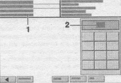
Using the keyboard, enter "007" for the display group number in information field "2" and confirm your choice by pressing the "Q" key. (The pistons are returned to their original position.) To exit the input form, press the lower left key, which has a green arrow on it. Turn off the ignition. Raise the car. Remove the wheels. Disconnect the brakes. hose and wiring harness from the bracket on the beam. Unscrew screws "16 and 17" on the brake caliper. Remove the brake caliper with the pads and brake pads. caliper. Do not leave brake. caliper with bracket hanging on the brake. hose. Use a suitable cable tie or wire to secure it to the body. The brake hose must not be subject to stress. With the brakes released. do not press the brake pedal or the parking brake button while holding the caliper. brakes.
Installation
Use new screws. Carefully push the brake. caliper with bracket with installed brake pads. disc. Secure the brake. the bracket with new screws "16 and 17". To tighten the lower screw "16", use a standard extension. For the top screw "17" no extension is required. It is necessary to bend the fender liner a little. Insert brake. hose and wiring harness into the bracket on the beam. Check that the brakes are installed correctly. hose in the bracket. The brake hose should not spontaneously separate from the bracket. Install the wheels. Turn on the ignition. Display of data on the tester display: in field "1" a prompt to enter the indication group is displayed; field "2" displays the keyboard for input. Using the keyboard, enter "006" for the display group number in information field "2" and confirm your choice by pressing the "Q" key. (The pistons should move.) To exit the input form, press the lower left key, which has a green arrow on it. With the ignition off, connect the tester -VAS 5051 B- or "VAS 5052" to the 16-pin diagnostic connector of the vehicle.
Replacement rear. brake calipers
When replacing the rear. brake caliper removal execution. no electric motor required. The new brake caliper is supplied assembled with a new electric motor. With the ignition off, connect the "VAS 5051B" or "VAS 5052" tester to the 16-pin diagnostic connector of the vehicle. Turn on the ignition. Turn off the parking brake. brake. Check coding and adjust if necessary. Interrogate the fault memory, eliminate detected faults, erase errors from the fault memory. Select function "053 - Parking brake". Select function "006 - Basic setting". Data display on the tester display: field "1" displays a prompt to enter the display group; field "2" displays the keyboard for input. Using the keyboard, enter "007" for the display group number in information field "2" and confirm your choice by pressing the "Q" key. (The pistons are returned to their original position.) To exit the input form, press the lower left key, which has a green arrow on it. Turn off the ignition. Install the spacer "VAG 1869/2" between the brake pedal and the driver's seat, so that the pedal is pressed at least 60 mm. In this case, the main brake valves. the cylinders will close and the expansion tank will not be empty. Raise the car. Remove the wheels. Connect the bleeder hose from the container to the rear bleeder nipple. brake caliper. Open the rear bleed screw. brake caliper to relieve pressure in the brake. syst.. Close the bleed nipple. Spacer "VAG 1869/2" do not remove. Disconnect the parking sensor connector. brakes. Disconnect the brake. hose and wiring harness from the bracket on the beam. Remove the rear brakes. pads. Mark the position of the brake pads. pads, if they will still be used. They must be installed back in the same places, otherwise uneven distribution of brakes will occur. forces between the wheels! After a long drive, it is recommended to turn on the electric. mechanical parking brake. Play caused by reduction in brake thickness. brake pads, is corrected automatically every 1000 km, if this has not been done earlier when the ERV is turned on. Unscrew the brake pads. pipeline from brake. caliper. Remove the brake caliper from the car. When replacing the rear. brake caliper removal execution. no electric motor required. The new brake caliper is supplied assembled with a new electric motor.
Installation
Use new screws. Connect and tighten the brake. brake hose. caliper. Install the rear brakes. pads. Secure the brake pads. caliper with new screws "4". To tighten screws "4", use a torque wrench "VAG 1331" with a socket "VAG 1331/3". Parking connector. connect the brakes only after tightening the screws. Connect the electrical wire to the parking brake. Insert brake. hose and wiring harness into the bracket on the beam. Check that the brakes are installed correctly. hose in the bracket. The brake hose should not spontaneously separate from the bracket. After each brake replacement. press the brake pedal hard several times. This is necessary in order to brake. the pads have taken their working position. Remove the spacer "VAG 1869/2". Pump up the brakes. system. Install the wheels. Turn on the ignition. Display of data on the tester display: in field "1" a prompt to enter the indication group is displayed; field "2" displays the keyboard for input. Using the keyboard, enter "006" for the display group number in information field "2" and confirm your choice by pressing the "Q" key. (The pistons should move.) To exit the input form, press the lower left key, which has a green arrow on it. With the ignition off, connect the "VAS 5051B" or "VAS 5052" tester to the 16-pin diagnostic connector of the vehicle.
Removal and installation rear brakes. pads
Mark the brake position. pads, if they will still be used. They must be installed back in the same places, otherwise uneven distribution of brakes will occur. forces between the wheels! After a long drive, it is recommended to turn on the electric. mechanical parking brake. Play caused by reduction in brake thickness. the brake pads are automatically repaired every 1,000 km, unless this has already been done when the EPB is turned on. With the ignition off, connect the "VAS 5051B" or "VAS 5052" tester to the vehicle's 16-pin diagnostic connector. Turn on the ignition. Turn off the parking brake. brake. Check coding and adjust if necessary. Interrogate the fault memory, eliminate detected faults, erase errors from the fault memory. Select function "053 - Parking brake". Select function "006 - Basic setting". Data display on the tester display: field "1" displays a prompt to enter the display group; in field "2" the keyboard for input is displayed. Using the keyboard, enter "007" for the display group number in information field "2" and confirm your choice by pressing the "Q" key. (The pistons are returned to their original position.) To exit the input form, press the lower left key, which has a green arrow on it. Turn off the ignition. Raise the car. Remove the wheels. Disconnect the brake. hose and wiring harness from the bracket on the beam. Unscrew the brake mounting bolts. calipers, holding the guides from turning.
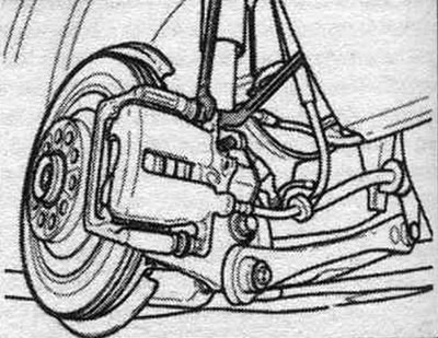
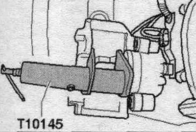
Remove the brake caliper. Do not leave the brake caliper in place. caliper hanging on the brake. hose, use a suitable cable tie or wire to secure it to the body. The brake hose must not be subject to stress. With the brakes released. do not press the brake pedal while holding the caliper. Remove the pads. Remove the brake pad holders. Press the piston into the caliper. To do this, use a tool to press in the brake piston. cyl. T10145. Do not allow the piston to tilt when pressing in.
Installation
For cleaning brakes. use only alcohol for support. Insert the support springs. Remove the existing protective film from the back of the brake pads. pads.
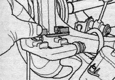
Install brake. pads.
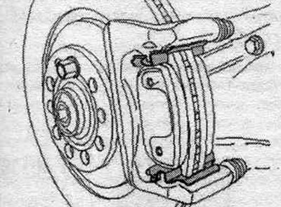
Make sure that the brakes are applied. the pads are correctly positioned in the "arrow" holders. The brake pads should be positioned between both retaining tabs of the holder to ensure clearance between the disc and the pad.
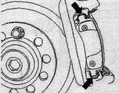
Install brake. support. The repair kit contains. self-locking bolts, which must be used. Secure the brake. support using new self-locking bolts. Use a torque wrench with a socket to tighten the screws "VAG 1331/3". Insert brake. hose and wiring harness into the bracket on the beam. Check that the brakes are installed correctly. hose in the bracket. The brake hose should not spontaneously separate from the bracket. Install the wheels. Check the brake level. liquids, top up if necessary. Turn on the ignition. Display of data on the tester display: in field "1" a prompt to enter the indication group is displayed; in field "2" the keyboard for input is displayed. Using the keyboard, enter "006" in the information field "2" for the display group number and confirm your choice by pressing the "Q" key. (The pistons should move.) To exit the input form, press the lower left key, which has a green arrow on it. With the ignition off, connect the "VAS 5051B" or "VAS 5052" tester to the 16-pin diagnostic connector of the vehicle.
Removal and installation rear brakes. disks
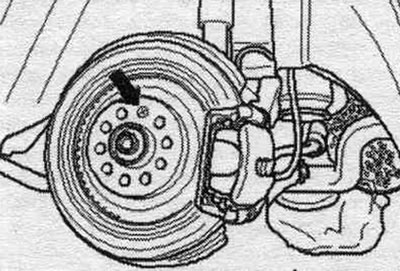
Raise the car. Remove the wheels. Disconnect the brakes. hose and wiring harness from the bracket on the beam. Remove the brake caliper with the bracket and pads. Do not leave brakes. caliper with bracket hanging on the brake. hose, use a suitable cable tie or wire to secure it to the body. The brake hose must not be subject to stress. With the brakes released. do not press the brake pedal while holding the caliper. Unscrew the brake disc fixing bolt "arrow" while holding the disc. Remove the brake disc from the hub. Do not distort the brake. disk when removing it from the hub.
Installation
Clean the brake before installation. disk, hub and mating surfaces. Install brake. disk on the hub. Screw in the "arrow" fixing bolt and tighten it. Install brake. caliper with bracket. Insert brake. hose and wiring harness into the bracket on the beam. Check that the brakes are installed correctly. hose in the bracket. The brake hose should not spontaneously separate from the bracket. Install the wheels.
Replacing rear brakes. disks
Raise the car. Remove the wheels. Disconnect the brakes. hose and wiring harness from the bracket on the beam. Remove the rear brakes. brake pads. Unscrew screws "16 and 17" and remove the brake pads. bracket. Unscrew the "arrow" fixing bolt while holding the disk. Remove the brake disc from the hub.
Installation
Clean the brake before installation. disk, hub and mating surfaces. Install brake. disk on the hub. Screw in the "arrow" fixing bolt and tighten it. Install the rear brake. bracket. Screw in and tighten screws "16" and "17". Use a standard extension to tighten the lower screw "16". For the top screw "17" no extension is required. It is necessary to bend the fender liner a little. Install rear brakes. pads. Insert brake pads. hose and wiring harness into the bracket on the beam. Check that the brakes are installed correctly. hose in the bracket. The brake hose should not spontaneously separate from the bracket. Install the wheels.
(The full version is posted on the resource: «AUDIMANUAL»)