



Table of contents: Parts and components of brakes… ↓ Removal and installation the front… ↓ Replacing the front brake. fN-3… ↓ Removal and installation of front.… ↓ Removal and installation of front.… ↓
Parts and components of brakes front. fN3-57 wheels
Note: Install the entire repair kit. After replacing the brakes. press the brake pedal hard several times to get the pads into their working position. To bleed brakes. use a liquid-resistant container to remove air from the tank.
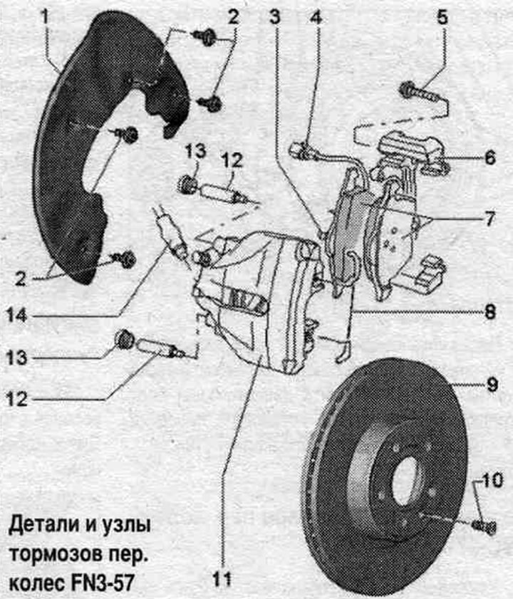
1. Brake shield.
2. Bolt: 18 Nm.
3. Pressure spring: must be in the brake. piston.
4. Connector: remove from the holder when replacing the pads.
5. Bolt: 196 Nm.
6. Brake caliper: attached to the steering knuckle.
7. Brake pads: Before installing the pads, clean the guide surfaces and apply a film of polyurea-based grease -G 052142 A2-; front left brake wear indicator. pads; when wear is detected, a warning lamp lights up in the instrument cluster; replace all pads for the corresponding axle. Inner shoe (with expansion spring) marked with an arrow. The arrow must point in the direction of brake movement. disc when the car is moving forward. If installed incorrectly, noise may be heard. Before installation, remove the existing brake pad on the rear side. apply adhesive film to the pads before installing new brake pads. thoroughly clean the brake pads from any dirt. support (degrease). In this case, pay special attention to removing any possible film residue from the outer surface of the brakes. pads.
8. Spring: Before installing the pads, clean the guide surfaces and apply a film of polyurea-based grease -G 052 1 42 A2-; insert into both holes of the brake housing. caliper. After installation, press the support spring into both holes under the brake caliper bracket. brake pads. If installed incorrectly, wear on the outer pad cannot be properly compensated for, leading to increased brake pedal travel.
9. Brake disc: replace all pads for the corresponding axle; to remove, first remove the brake. support.
10. Bolt: 5 Nm.
11. Brake caliper: for replacing brakes. unscrew the brake pad from the holder bracket.
12. Guide pin: 30 Nm.
13. Plug: To remove, remove the guide pins; after installation, insert the guide pins.
14. Brake hose; to replace brakes. unscrew the brake pads. no hose required; screwed into the brake housing. calipers; to the brake caliper. 20 Nm.
Removal and installation the front brake. calipers with brakes. fN-3 bracket
Raise the car. Remove the wheels. Disconnect the brakes. hose from the bracket. Disconnect the wear indicator from the left brake. caliper. Unscrew screws "5" of the brake caliper. Remove the brake caliper with pads and brake. caliper. Do not leave brake. caliper with bracket hanging on the brake. hose, use a suitable cable tie or wire to secure it to the body. The brake hose must not be subject to stress. With the brakes released. do not press the brake pedal while holding the caliper.
Installation
Use only new screws. Carefully push the brake. caliper with bracket with installed brake pads. disc. Secure the brake. bracket with new screws "5". Insert the brake. hose into the bracket. Install the wheels.
Replacing the front brake. fN-3 calipers
Install the spacer "VAG 1869/2" between the brake pedal and the driver's seat, so that the pedal is pressed at least 60 mm. In this case, the main brake valves. the cylinders will close and the expansion tank will not be empty. Raise the vehicle. Remove the wheels. Connect the bleeder hose to the front brake bleeder nipple. caliper. Open the bleed screw of the front brake caliper. brake pressure relief calipers. syst.. Close the bleed nipple. Do not remove the "VAG1869/2" spacer. Remove the brake pads. Mark the position of the brake pads. pads, if they will still be used. They must be installed back in the same places, otherwise uneven distribution of brakes will occur. forces between the wheels! The brake disc is secured with a screw. Unscrew the brake. brake hose. caliper. Remove the brake caliper from the car. Unscrew the screws "5" of the brake caliper, while holding the caliper. Remove the brake caliper.
Installation
Use only new screws. Install brake. bracket. Secure the brake. bracket with new screws "5". Connect and tighten the brake. brake hose. caliper. Install brake. pads. After each replacement of brake pads. press the brake pedal hard several times. This is necessary in order to brake. the pads have taken their working position. Remove the spacer "VAG 1869/2". Pump up the brakes. syst.. Install wheels.
Removal and installation of front. fN-3 brake pads
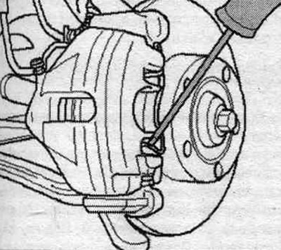
Replace all pads for the corresponding axle. Raise the car. Remove the wheels. Mark the position of the brakes. pads, if they will still be used. They must be installed back in the same places, otherwise uneven distribution of brakes will occur. forces between the wheels! Remove plugs "13". In the car, there are brake wear sensors. disconnect the connector "4" from the front left of the pads. Bend the locking tab on the bottom of the connector and then rotate it 90°. Disconnect the bottom of the wear sensor connector from the bracket. Use a screwdriver to pry it out of the brake housing. caliper support spring.
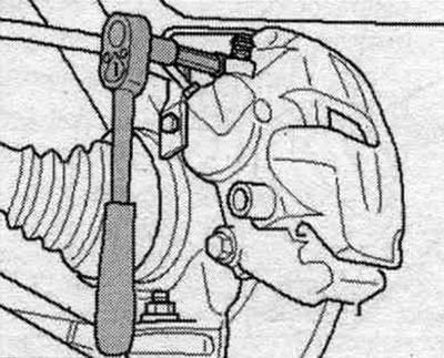
Unscrew and remove both guides "12" from the brake caliper. Secure the brake. support on the body using suitable wire. The brake hose must not be subject to stress. Remove the brake. pads from the brake housing. calipers and brackets. With the brakes released. do not press the brake pedal while holding the caliper.
Installation
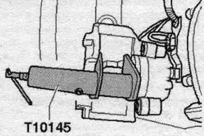
Clear brake. caliper. For cleaning brakes. use only alcohol for support. Before installing new brakes. press the pistons into the cylinders using a special tool. Before this, pump out the brakes using a special device. liquid from the expansion tank. Otherwise, pouring out the brakes. liquids may cause damage. Press the piston into the caliper. To do this, use a tool to press in the brake piston. cyl. T10145.
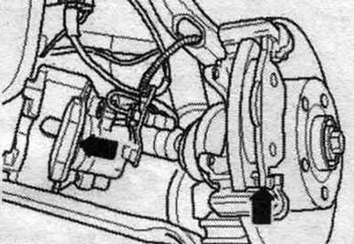
Insert brake. shoe with a retaining spring into the brake housing. caliper (piston). Inner pad (with expansion spring) marked with an arrow. The arrow must point in the direction of brake movement. disc when the car is moving forward. If installed incorrectly, noise may be heard. Remove the existing protective film from the back of the brake pads. pads. Install the outer brake pads. brake shoe. bracket.
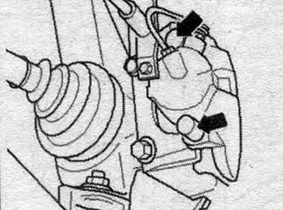
Insert into the brake housing. caliper both guide pins and tighten. Install both arrow caps.
Insert the support spring into the brake housing. caliper. After installation, press the support spring into both holes under the brake caliper bracket. brake pads. If installed incorrectly, wear on the outer pad cannot be properly compensated for, leading to increased brake pedal travel. After installing the brakes. press the brake pedal hard several times to apply the brake pads. This is necessary to ensure that the brakes are applied. the pads have taken their working position. Check brake fluid level. liquids, top up if necessary.
Removal and installation of front. fN-3 brake discs
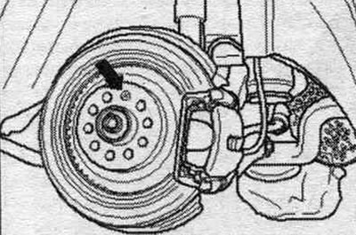
Raise the car. Remove the wheels. Remove the front brake. caliper with bracket and pads. With the brakes released. do not press the brake pedal while holding the caliper. Do not leave brakes. caliper with bracket hanging on the brake. hose, use a suitable cable tie or wire to secure it to the body. The brake hose must not be subject to stress. Unscrew the brake disc fixing bolt "arrow" while holding the disc. Remove the brake disc. Do not tilt the brake disc. disk when removing it from the hub.
Installation
Clean the brake before installation. disk, hub and mating surfaces. Install brake. disk on the hub. Screw in the "arrow" fixing bolt and tighten it. Install the front brake. caliper with bracket and pads. Install the wheels.