



Table of contents: Removal and installation the brake… ↓ Removal and installation the ESP… ↓ Removal and installation of the… ↓ Hydraulic parts and assemblies,… ↓ Removal and installation hydraulics,… ↓ Parts and components of speed… ↓ Removal and installation of front.… ↓
Removal and installation the brake light switch
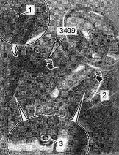
Once removed, the brake light switch can be used again. The brake light switch adapts itself. No calibration is required after installation. Remove storage compartments from the driver's side "1...3".
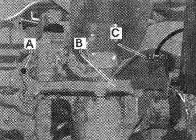
Disconnect the air duct wiring. for feet "C". Remove the air duct "A-B". Disconnect the brake light switch connector.
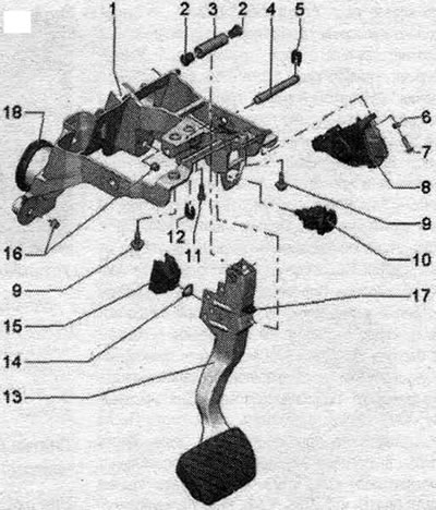
If possible, do not remove the stop "17" from the brake pedal, since the socket of the brake light switch "10" may be damaged if the brake pedal is moved abruptly when unlocking. Press the brake light switch rod "10" with your finger until it stops. While pressing the rod, turn the rotary element of the brake light switch to the left until it stops to unlock the switch. When the brake light switch is unlocked, the plunger should be recessed. After unlocking, release the switch rod. Insert the T40168 puller between the switch rod and the brake pedal. The cone of the puller should be directed towards the driver's seat. The puller's recess should align with the brake light switch's protrusion. Press the "T40168" puller toward the brake light switch. This will release the three brake light switch latches. Remove the brake light switch from its socket.
Installation
Do not remove the brake pedal stop "17" as there is a risk of damaging the brake light switch socket "10" when releasing the brake pedal.
During installation of the brake light switch, the position of the rod is adjusted automatically. When installing, the brake pedal must be in its original position and not move. The brake pedal must be connected to the brake booster. Insert the brake light switch into the brake pedal socket and press lightly. The brake light switch must be securely fastened with three clips. The switch should not rotate in the socket
brake pedals. During installation of the brake light switch, the position of the rod is adjusted automatically. Turn the colored rotary element of the brake light switch to the right until it stops to lock the switch. Connect the electrical wire to the servo motor. Install the air duct for blowing space. for legs "A-B". Tighten the screw of the air duct "A". Connect the wiring of the air duct for blowing space. footrest "C". Install storage compartments on the driver's side "1-3". After installing the brake light switch, check its operation before driving.
Removal and installation the ESP sensor unit "G419"/G536
The ESP sensor unit is sensitive to strong vibrations and impacts. Strong vibrations and impacts can damage the ESP sensor unit. If the ESP sensor unit is dropped from a height, its proper operation will be impaired; such a unit should not be installed. The ESP sensor unit "G536" is not installed on all models. The ESP sensor unit "G419" and the ESP sensor unit "G536" are installed under the left seat on all models. The arrow on the sensor block should point in the direction of travel.
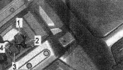
Remove the left seat. Move the carpet crossbar to the side. If the jumper does not pass through the carpet, cut the jumper with a sharp knife. Remove the footwell air duct. Disconnect connectors "2" or "4". Unscrew the sensor block mounting nuts. Remove the ESP sensor unit "G419" "1" or the ESP sensor unit "G536" "3" from the vehicle in an upward direction.
Installation
Install the ESP sensor unit "G419" "1" or the ESP sensor unit "G536" "3" into the mounting locations, moving from top to bottom. When installing the sensor unit, it is necessary to ensure its correct position on the bracket, eliminating the appearance of internal stress in it. Attach and tighten the sensor block mounting nuts. Connect connectors "2" or "4". Install the air duct space. for feet. Install the carpet crossbar with a downward movement. Install the left seat. After replacing the sensor block, a basic installation is required (calibration) the following sensors: lateral acceleration sensor G200, longitudinal acceleration sensor G251. To do this, use the VAS 5051 B or VAS 5052 tester. Select on the display: Chassis, Brake system. 01 - Self-diagnostic systems, 03 - brake electronics. system. Select the following functions on the display: Calibrate the lateral acceleration sensor G200, calibrate the longitudinal acceleration sensor G251. Finally, perform an ESP system test and a test drive.
Removal and installation of the steering angle sensor "G85"
The steering angle sensor "GB5" is located between the steering wheel and the steering column switch unit. Set the wheels to the straight-ahead position. Slip ring assembly "1".
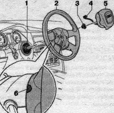
Remove the Airbag and steering wheel: secured to the turn signal, high beam, low beam and light signal switch, secured to the contact ring. It is prohibited to rotate the elements of the slip ring assembly relative to each other. Remove the steering column control unit.
Installation
Installation in reverse order. Install the airbag and steering wheel. Calibrating the G85 steering angle sensor. Use the VAS 5051 B or VAS 5052 tester. Select the desired function on the display. Finally, carry out a system test of the ESP and a test drive.
Hydraulic parts and assemblies, block N55 with control unit J104
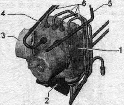
1. ABS hydraulic unit "N55" with ABS control unit "J104"; installation location in the motorcycle. compartment on the front left; hydr., block "N55" with built-in pressure sensor in the brake. the G201 system and the J104 control unit form a hydraulic module, the parts form a non-detachable unit; do not disconnect the connector until the self-diagnosis is completed; before disconnecting the connector, turn off the ignition; brake pressure sensor. the "G201" system is built into the "N55" hydraulic unit and cannot be replaced separately. The N55 hydraulic unit and the J104 control unit are made as a single part.
2. ESP bracket: The bracket cannot be removed.
3. Control unit connector "J104".
4/5. Brake line to the main brake. cylinder. 14 Nm.
6. Brake lines: connects the hydraulic unit and the front right brake. caliper, 14 Nm; connects the hydraulic unit and the front left brake. caliper, 14 Nm; connects the hydra, block and rear. left brake. caliper, 14 Nm; connects the hydra, block and rear. right brake. caliper. 14 Nm.
Removal and installation hydraulics, block N55 with control unit J104
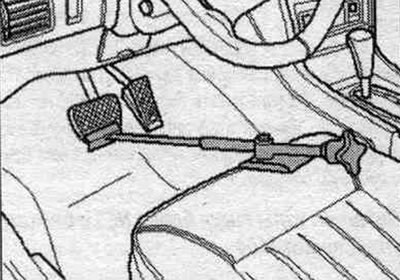
The hydraulic unit N55 with control unit J104 is located in the engine. compartment on the front left. Disconnecting the control unit J104 from the hydraulic unit N55 is not permitted. Read and write the control unit version. Use the VAS 5051B or VAS 5052 tester. Disconnect the battery, taking into account the head unit coding. Install the spacer "VAG 1869/2" between the brake pedal and the driver's seat, so that the pedal is pressed at least 60 mm. In this case, the main brake valves. the cylinders will close and the expansion tank will not be empty. Connect the bleeder hose to the bleed nipple of the front left brake. caliper. Connect the bleeder tank hose to the rear bleeder nipple. left brake. calipers. Open the bleed nipples of the front left and rear. left brake. calipers to relieve pressure in the hydraulic block "N55". Tighten the bleed nipples of the front left and rear. left calipers. Spacer "VAG 1869/2" do not remove.
Press up the locking device of the control unit connector "1".
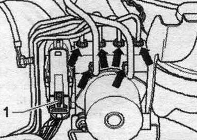
Move the retaining clip in the direction of the arrow and disconnect the connector.
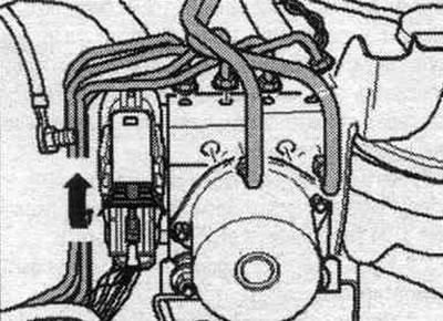
To prevent leaking brake fluid from entering. to remove any liquids from other parts, place a sufficient amount of rags that do not leave fibers under the control unit "J104" and the hydraulic unit "N55". Mark the brake lines. system for subsequent installation. Disconnect the brake. pipelines leading to the main brake. cylinder, from the hydraulic unit "N55". Unscrew the remaining "arrow" pipes from the hydraulic unit "N55". Close the brake lines and threaded holes with the plugs from the repair kit. Carefully remove the hydraulic unit "N55" together with the control unit "J104" from the bracket in an upward motion. When disconnecting the ESP unit from the bracket, make sure that the rubber stops do not fall into the motorcycle. compartment. Install the hydraulic unit "N55" with the control unit "J104" on a flat, clean surface so that the control unit is located below. After removing the hydraulics, block "N55" with the control unit "J104", close the threaded holes and brakes with plugs. pipelines.
Installation
Installation in reverse order. The supplied hydraulic block "N55" is filled with brake fluid. liquid. Remove the plugs from the new "N55" hydraulic block only immediately before connecting the corresponding brake fluid. pipeline. Removing plugs from the hydraulic unit "N55" without connecting the corresponding brake. pipeline leads to brake fluid leakage. fluid. This will not ensure complete bleeding of the brakes. system.. All rubber stops must be installed in the bracket. Install the hydraulic unit "N55" with the control unit "J104" into the bracket on the vehicle in a downward motion. When installing the ESP unit into the bracket, hold the rubber stops to prevent it from falling out. Connect the pipelines according to the markings. Connect all "arrow" lines to the "N55" hydraulic unit. All brake lines to the hydraulic unit: 14 Nm. Connect the connector to the "J104" control unit. Press the retaining clip down until it audibly locks into place. Press the lock "1" down until it locks into place. Remove the spacer "VAG 1869/2". Pump up the brakes. system.. After connecting the pipelines to the hydraulic unit "N55", perform diagnostics of the actuators. To do this, use the VAS 5051 B or VAS 5052 tester. If the J104 control unit has been replaced, it must be recoded. Use the tester -VAS 5051B- or "VAS 5052". Select on the display: Chassis, Brake system, 01 - Self-diagnostic systems, 03 - Brake electronics. syst. Select Functions on the display. J104 - ABS/ASR/ESP control unit, J104 - ABS/ASR/ESP control unit, functions, J104 - Control unit, coding. After replacing the J104 control unit, the following sensors must be calibrated: steering angle sensor "G85", lateral acceleration sensor "G200", longitudinal acceleration sensor "G251". Use the "VAS 5051 B" or "VAS 5052" tester. Select on the display: Chassis, Brake system, 01 - Self-diagnostic systems, 03 - Brake electronics. syst.. Select on the display Functions: J104 - ABS/ASR/ESP control unit, J104 - ABS/ASR/ESP control unit. functions. Finally, carry out an ESP system test and a test drive.
Parts and components of speed sensors of the system. ABS/ESP
Front view from the right
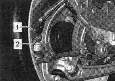
1. Speed sensors G45/G47.
2. Hexagon socket head bolt: 9 Nm.
Removal and installation of front. speed sensors G45/G47
The sensor ring/rotor is integrated into the bearing assembly and is not separately replaceable. Raise the vehicle. Unlock and disconnect the speed sensor connector "1". Remove screw "2". Remove the speed sensor from the steering knuckle.
Installation
Installation in reverse order. Before installation, clean the hole and apply a small amount of G 000 650 plastic grease to the sensor. After installation, turn the wheels fully left and right and check that the sensor wire is not stretched.
Removing and installing rear speed sensors G44/G46
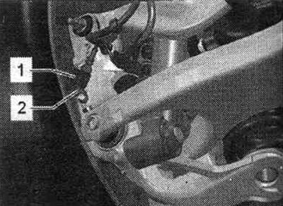
Rear view from the left
1. Speed sensors G44/G46.
2. Hexagon socket head bolt: 9 Nm.
Raise the vehicle. Unlock and disconnect the speed sensor connector "1". Remove screw "2". Remove the speed sensor from the steering knuckle.
Installation
Installation in reverse order. Before installation, clean the hole and apply a small amount of plastic grease G 000 650 to the sensor.
(A link to the original source is available on the website AUDImanual)