



Table of contents: Steering knuckle, wheel bearing… ↓ Removal and installation the wheel… ↓ Removal and installation the shock… ↓
Steering knuckle, wheel bearing module, shock absorber, front-wheel drive vehicle
Note: On front wheel drive vehicles, 2 different wheel bearing housings are used. For some time, a "Front-wheel drive" wheel bearing housing and an "All-wheel drive" wheel bearing housing were installed. Therefore, before starting work, it's important to check which of the two wheel bearing housings is actually installed.
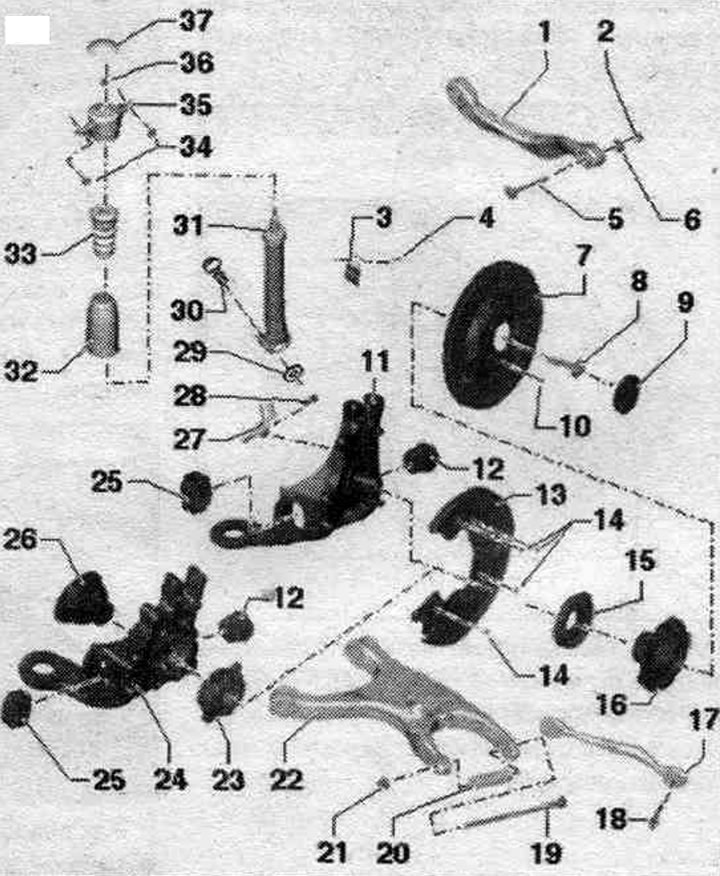
1. Upper wishbone.
2. Nut: 95 Nm; replace when removing: tighten only when the vehicle is in a no-load position.
3. Holder: for brake hose, caliper line harness and rear harness. speed sensor.
4. Bolt: 10 Nm.
5. Bolt.
6. Eccentric washer.
7. Brake disc.
8. Flange bolt: 200 Nm + 180°; replace when removed.
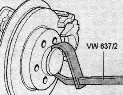
9. Protective cap: remove using the hub cap puller "VW 637/2"; replace when removed.
10. Bolt: 5 Nm.
11. Hub bearing housing: with axle journal. At one point, front-wheel drive vehicles were equipped with a wheel bearing housing for all-wheel drive vehicles. Mixed installation of 2 racks of different types is not allowed. At a certain point, front-wheel drive vehicles were equipped with a steel wheel bearing housing instead of an aluminum one. Mixed installation of 2 racks of different types is not allowed.
12. Silent block: cannot be replaced separately.
13. Brake safety shield.
14. Bolt: 10 Nm.
15. External seal.
16. Hub bearing assembly: The hub bearing assembly cannot be repaired.
17. Cross rod: take into account the different designs: aluminum and steel, compliance; simultaneous installation of 2 racks of different types is not allowed.
18. Bolt: 90 Nm + 90°; replace when removed; tighten only when the vehicle is in a no-load position.
19. Bolt: 120 Nm + 360°; replace when removed; tighten only when the vehicle is in a no-load position. If the bolt is removed, then the wheel alignment angle must be adjusted.
20. Spacer tube: replace when removed.
21. Nut: Replace when removed. If the nut becomes loose, the wheel alignment angle needs to be adjusted.
22. Lower wishbone.
23. Ball bearing.
24. Hub bearing housing: without axle journal. At one point, front-wheel drive vehicles were equipped with a wheel bearing housing for all-wheel drive vehicles. Mixed installation of 2 racks of different types is not allowed.
25. Silent block.
26. End of the hinge shaft.
27. Bolt: 9 Nm.
28. ABS rear speed sensor.
29. Washer: designed to protect against corrosion; always use together.
30. Bolt: 150 Nm +180°; replace when removed; tighten only when the vehicle is in a no-load position.
31. Shock absorber.
32. Anther.
33. Emphasis.
34. Bolt: 50 Nm + 45°; replace when removed.
35. Upper shock absorber support.
36. Nut: 35 Nm: replace when removed.
37. Protective cap.
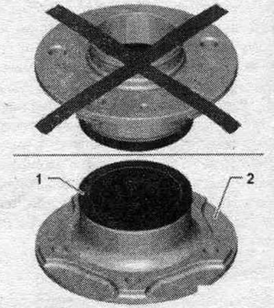
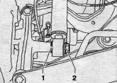
Hub bearing "1" must always point upwards. Always place the hub bearing assembly on wheel hub "2".
Removal and installation the wheel bearing housing
Before starting work, measure the distance "a" from the center of the wheel to the lower edge of the wheel arch while the wheels are still on the car.
Only for vehicles with a cardan shaft end: Loosen and unscrew the "arrow" bolt.
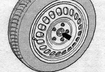
All
Place the car on a lift.
Only when replacing the wheel bearing housing: Lightly tap the dust cap loose on the wheel bearing cap puller "VW 637/2".
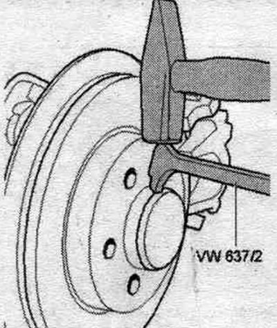
Remove the dust cap using the hub cap puller "VW 637/2". Loosen the flange bolt of the wheel bearing unit (loosen only on a vehicle standing on the wheels "risk of accident").
All
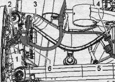
Remove the wheel. Unlock and remove plug "1" from the rear speed sensor. Unlock connector "3" of the electronic mechanical parking brake and remove it. Unscrew bolt "2" and remove holder "6" with wires. Remove the brake caliper and brake. disc. Secure the brake caliper to the body so that its weight does not press on the brake. hose or brake. highway and did not damage them.
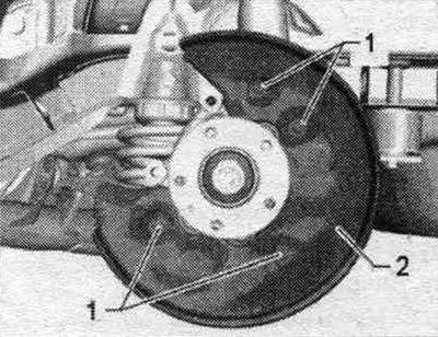
Only when replacing the wheel bearing housing: Loosen bolts "1" and brake shield "2". Removing the wheel bearing module by the outer ring (wheel hub) not allowed.
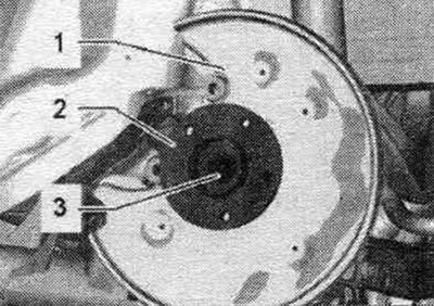
Gently pull wheel bearing module "2" through brake shield "1" from axle stub "3." If the wheel bearing module can be removed from the steering knuckle by hand, the wheel bearing module is OK and can be reinstalled.
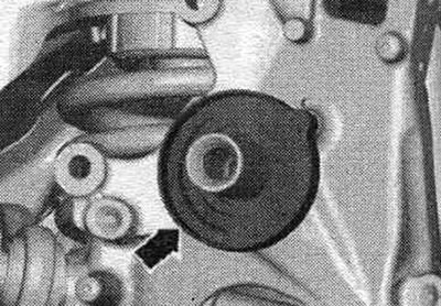
As soon as the axle journal is moved far enough, grasp the outer seal from behind "arrow". Remove the wheel bearing module and brake shield (both in the illustration not shown) through the outer seal "arrow".
Hub bearing "1" must always point upwards. Always place the hub bearing assembly on wheel hub "2". Cleaning the outer seal.
Remove the rear speed sensor "2". To do this, unscrew bolt "1".
All
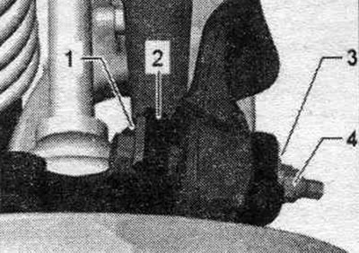
Remove the coil spring. Mark the position of bolt "1" in relation to hub bearing housing "2". Unscrew nut "4" and remove eccentric washer "3". Remove bolt "1".
Unscrew bolt "4".
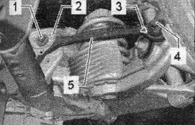
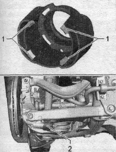
Unlock the locking tabs "1" and remove the stone protection "2".
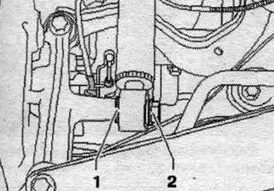
Unscrew bolt "1" and remove washer "2".
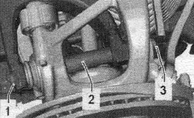
Unscrew nut "3". Unscrew bolt "1" and remove spacer tube "2". Remove the wheel bearing housing.
Installation
Installation in reverse order. Silent blocks have a limited torsional working range. Therefore, wheel suspension bolt connections should only be tightened when the vehicle is in the unloaded or standard suspension position. Raise the wheel support with the suspension in a static position on a vehicle with coil springs. Insert the hub bearing housing. Insert bolt "1" with spacer tube "2" and tighten nut "3". Do not use nut "3" to tighten the threaded connection. Tighten bolt "1". Install the coil spring. Install the caliper and brake. disk.
Only when replacing the wheel bearing housing: Install the speed sensor at the rear. Put on the outer seal and lubricate the arrow axle journal with a thin layer of plastic grease. Replace damaged (bent) protective caps. Damaged (dented) caps allow moisture to pass through. Therefore, use only the tools shown in the pictures.
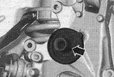
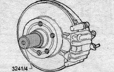
Install the protective cap using the mandrel -3241/4-.
All
Install the wheel. Tighten the wheel.
Only when replacing the wheel bearing housing: Tighten the wheel bearing assembly flange bolt (tighten only with the vehicle standing on its wheels "risk of accident"):
Removal and installation the shock absorber
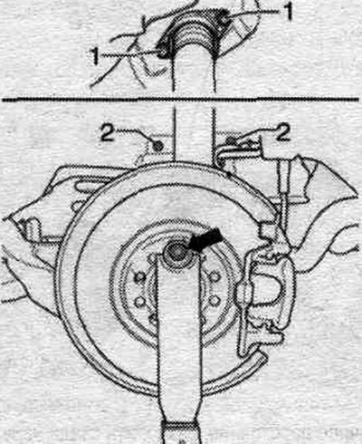
Before starting work, measure the distance "a" from the center of the wheel to the lower edge of the wheel arch while the wheels are still on the vehicle. Place the vehicle on a lift. Remove the wheel. Remove the wheel arch liner. Turn the hub upward so that one hole for the wheel bolt is at the top. Attach the "T10149" support mount with the "arrow" wheel bolt. Insert the "T10149" support mount into the tilting tool and slightly lift the wheel bearing housing. Unscrew bolts "1".
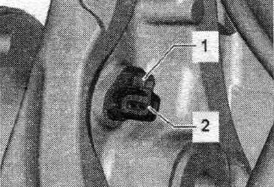
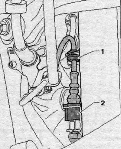
Only for vehicles with electric system. damping adjustment: Unlock and remove connector "2". Disconnect fastening "1".
All
Unlock the locking tabs "1" and remove the stone protection "2".
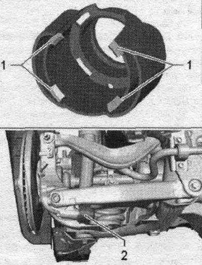
Unscrew bolt "1" and remove washer "2". Remove the shock absorber downwards.
Installation
Installation in reverse order. Install the wheel arch liner. Tighten the wheel.
[The original text is available on the website: audimanual.ru]