



Table of contents: Upper wishbone, tie rod, coil… ↓ Removal and installation the lower… ↓ Removal and installation the upper… ↓ Removal and installation the… ↓ Body level sensor ↓ Replacing the door sensor. clearance… ↓
Upper wishbone, tie rod, coil spring, lower wishbone, door sensor. clearance
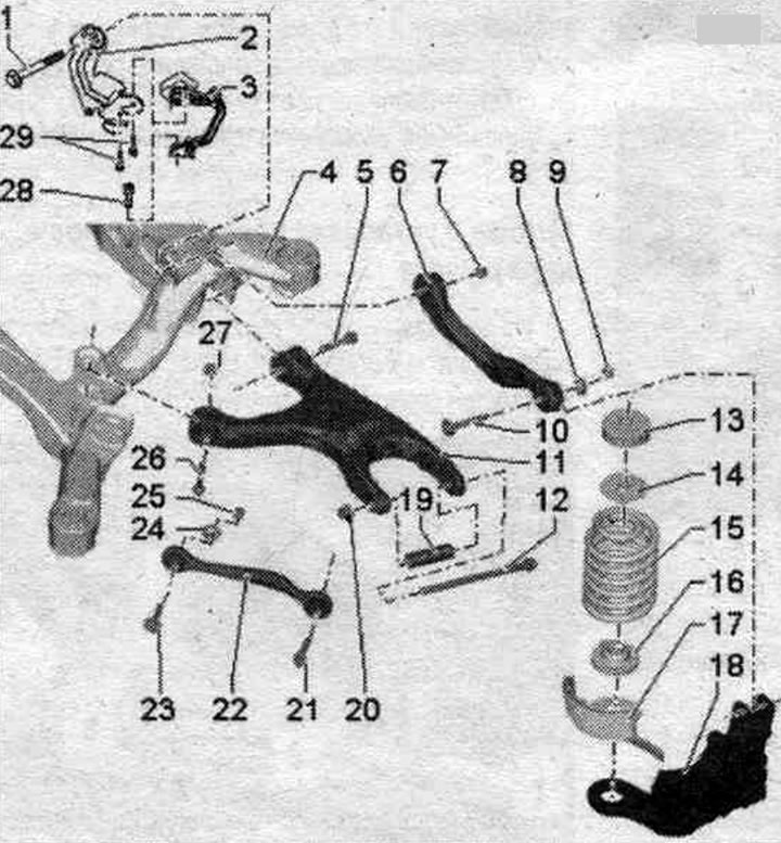
1. Bolt: 70 Nm + 180°: replace when removing; tighten only when the vehicle is in a no-load position.
2. Mounting bracket.
3. Rear left door sensor. clearance "G76": install only the same design sensor; complete with attachments; the sensor lever must be facing outward; replacement is carried out on the car; after loosening, check the basic headlight setting; after removing and installing the vehicle level sensor or loosening the rods on a vehicle with an electrical system. damping adjustment, the suspension should be re-adjusted to its standard position; if the control position is re-adapted on a vehicle with lane departure warning system, the lane departure warning system control unit "J759" must be recalibrated.
4. Subframe.
5. Bolt: 70 Nm + 180°; replace when removing: tighten only when the vehicle is in a no-load position.
6. Upper wishbone.
7. Nut: Replace when removed.
8. Adjusting washer.
9. Nut: 95 Nm; replace when removed; tighten only when the vehicle is in a no-load position.
10. Adjusting screw.
11. Lower wishbone.
12. Bolt: 120 Nm + 360°; replace when removed; tighten only when the vehicle is in a no-load position. If the bolt is removed, then the wheel alignment angle must be adjusted.
13. Upper spring spacer washer: 2 pieces are installed on aliroad.
14. Upper spring spacer: only installed on vehicles with rough road chassis.
15. Coil spring: It is necessary to take into account differences in the design of the chassis, see the vehicle data plate.
16. Lower spring gasket.
17. Stone protection for coil spring.
18. Hub bearing housing.
19. Spacer tube: replace when removed.
20. Nut: Replace when removed. It is prohibited to use a nut to tighten a threaded connection. If the nut becomes loose, the wheel alignment angle needs to be adjusted.
21. Bolt: 90 Nm + 90°; replace when removed; tighten only when the vehicle is in a no-load position.
22. Cross rod: take into account the installation position; take into account different designs: aluminum and steel; simultaneous installation of 2 racks of different types is not allowed.
23. Bolt.
24. Eccentric washer.
25. Nut: 95 Nm; replace when removed; tighten only when the vehicle is in a no-load position.
26. Bolt: 70 Nm + 180°; replace when removed; tighten only when the vehicle is in a no-load position.
27. Nut: Replace when removed.
28. Bolt; 9 Nm.
29. Bolt: 5 Nm.
Removal and installation the lower control arm
Before starting work, measure the distance "a" from the center of the wheel to the lower edge of the wheel arch while the wheels are still on the vehicle. Place the vehicle on a lift. Remove the wheel. Remove the coil spring. For a car with a door sensor. clearance "1" unscrew bolt "2".
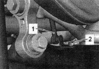
Unscrew bolt "4".
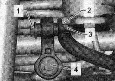
Loosen nut "3." Remove bolt "1" and remove spacer tube "2." If nut "3" loosens or bolt "1" is removed, the wheel alignment must be adjusted.
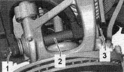
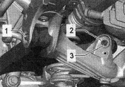
Unscrew the bolt. Unscrew the nut "3" and remove the bolt "2". Remove the lower wishbone.
Installation
Installation in reverse order. Silent blocks have a limited torsional working range. Therefore, wheel suspension bolt connections should only be tightened when the vehicle is in the unloaded or standard suspension position. Raise the wheel support with the suspension in a static position on a vehicle with coil springs. Insert the lower control arm and first tighten bolt "1." To ensure free rotation of bolt "2" during tightening, remove the aerodynamic trim and wheel spoiler. Insert bolt "2" and tighten nut "3". Insert bolt "1" with spacer tube "2" and tighten nut "3". Do not use nut "3" to tighten the threaded connection. Tighten bolt "1". Tighten the remaining threaded connections. Install the coil spring. Tighten the wheel. The need to adjust the wheel alignment angles. For vehicles with automatic headlight range control, perform basic headlight installation. After removing and installing the vehicle level sensor or loosening the rods on a vehicle with an electrical system. damping adjustment, the suspension should be re-adjusted to its standard position. If the control position is re-adapted on a vehicle with lane departure warning system, the lane departure warning system control unit "J759" must be recalibrated.
Removal and installation the upper control arm
Due to the inaccessibility of the internal threaded connection "1", the wishbone can only be removed with the subframe removed.
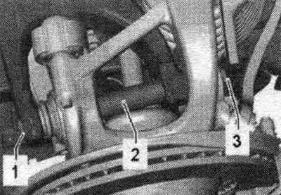
Before starting work, measure the distance "a" from the center of the wheel to the lower edge of the wheel arch while the wheels are still on the vehicle. Place the vehicle on a lift. Remove the wheels. Remove the subframe on a front-wheel drive vehicle. Remove the subframe on a vehicle with all-wheel drive. Mark, for example with a felt-tip pen, the position of the eccentric bolt "2" relative to the wheel bearing housing. Disconnect screw connections "1" and "2". Remove the upper control arm "3".
Installation
Replace bolts and self-locking nuts. Installation position of the upper wishbone on the subframe. Screw upper control arm "3" to threaded connection "1" by hand. Place a flat iron strip or straight bar "1" evenly on the upper control arm "arrow." Install upper control arm "2" so that the dimension a = 8 mm ±1 mm between bar "1" and the stamped corner of upper control arm "2.".
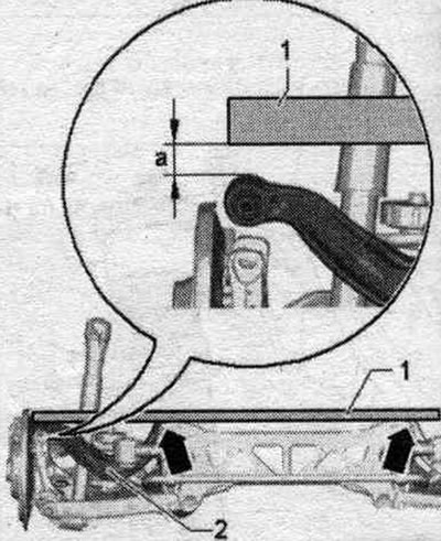
Tighten the threaded connection of the upper transverse arm "3" in this position on the subframe. Bolt the hub bearing housing to the wishbone and tighten the new nut to 20 Nm. Observe the installation instructions. position of eccentric washer "2". Install the subframe on a front-wheel drive vehicle. Install a subframe on a vehicle with all-wheel drive. Loosen bolt connection "1". Raise the wheel support to the vehicle's unladen weight position and tighten bolt connection "1".
Removal and installation the transverse steering wheel. traction
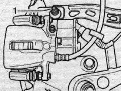
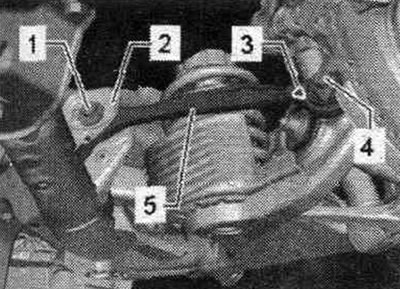
Before starting work, measure the distance "a" from the center of the wheel to the lower edge of the wheel arch while the wheels are still on the vehicle. Place the vehicle on a lift. Remove the wheel. First, unscrew bolt "4". Mark the position of bolt "1" in relation to subframe "2". Unscrew the nut and remove bolt "1". Remove the steering wheel. traction "5".
Installation
Installation in reverse order. Silent blocks have a limited torsional working range. Therefore, wheel suspension bolt connections should only be tightened when the vehicle is in the unloaded or standard suspension position. Raise the wheel support with the suspension in a static position on a vehicle with coil springs. Insert steering wheel. rod "5". Marking "3" should be on the outside. The tip of the marking "3" points upward. First, fully insert bolt "1" and align it according to the marking made earlier. Insert and tighten bolt "4". Hand-tighten a new nut for bolt "1". Tighten the nut for bolt "1" to the specified torque only after adjusting the wheel alignment.
Body level sensor
Car with electric system. regulation, damping and/or with gas discharge lamps are equipped with a dynamic headlight corrector as standard. The damping control system and the dynamic headlight range control require information about the compression and rebound stroke of the front springs to operate. suspension and rear. axles. To achieve this, the position of the left/right trapezoidal lever relative to the body is transmitted via a connecting rod to the rear. left door sensor. clearance "G76" and rear right door sensor. clearance "G77". They transmit electrical signals to the control unit of the system. electrical control, damping "J250" and/or left/right gas discharge lamp control unit -J343/344-. On the front axle from the road sensor. front left "G78" clearance and door sensor. front right clearance "G289" these signals are transmitted to the control unit of the system. electrical control, damping "J250" and/or to the left/right gas discharge lamp control units -J343/344-. These signals are necessary to determine the vehicle level. The automatic headlight range control reacts automatically to changes in road. clearance.
The vehicle level may change in the following situations: working with a trailer; various vehicle load conditions; the vehicle is unloaded, the vehicle is partially or fully loaded.
On vehicles with an electric system. adjustment, damping adaptation of the adjustment position and checking of the main headlight adjustments is essential in the following cases: the lower control arm was removed and installed or replaced, the upper wishbone was removed and installed or replaced, the subframe was replaced, installation work was carried out on the vehicle level sensor, the vehicle level sensor was replaced, the coil springs were replaced, the fastening of the connecting rod of the road sensor was loosened. clearance of the car on the lower wishbone.
On vehicles with an electric system. reg, damping adjustment position has been re-adapted. If the control position is re-adapted on a vehicle with lane departure warning system, the lane departure warning system control unit "J759" must be recalibrated.
Replacing the door sensor. clearance with the subframe installed
Remove the wheel. Disconnect connector "3". Unscrew bolt "1". Unscrew bolts "2" with a bent wrench. Be careful not to damage the mounting plate. Remove the door sensor. clearance of the vehicle. Install only a sensor of the same design.
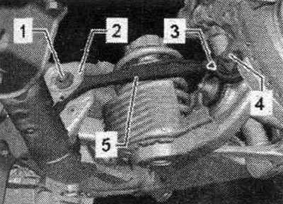
Treat and install the spare part accordingly. Screw in bolts "2" using a wrench with a bent handle. Be careful not to damage the mounting plate. When tightening screws "2", hold the vehicle level sensor. The sensor lever should be facing outward. Screw in bolt "1". Connect plug "3". Perform basic headlight adjustment. After removing and installing the vehicle level sensor or loosening the rods on a vehicle with an electrical system. damping adjustment, the suspension should be re-adjusted to its standard position. If the control position is re-adapted on a vehicle with lane departure warning system, the lane departure warning system control unit "J759" must be recalibrated.