



Table of contents: Removal and installation the… ↓ Replacement of silent block and… ↓ Replacing the front silent block or… ↓ Replacement rear. silent block or… ↓
At a certain point, front-wheel drive vehicles were equipped with a subframe for all-wheel drive vehicles.
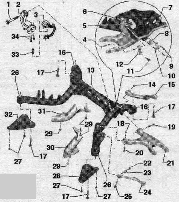
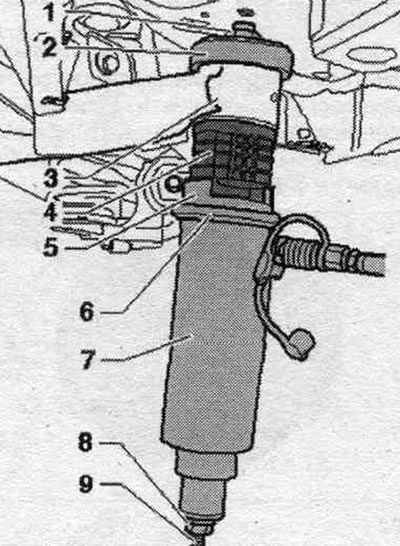
1. Bolt: 70 Nm + 180°; replace when removed; tighten only when the vehicle is in a no-load position.
2. Mounting bracket.
3. Rear left door sensor. clearance "G76" install a sensor of the same design only; complete with attachments; the sensor lever must be facing outward; replacement is carried out on the car; after loosening, check the basic headlight setting; after removing and installing the door sensor. clearance or detachment of rods on vehicles with an electric system. reg, damping should be readjusted to the adjustment position; if the control position is re-adapted on a vehicle with lane departure warning system, the lane departure warning system control unit "J759" must be recalibrated.
4. Bolt: 40 Nm + 90°; replace when removed; tighten only when the vehicle is in a no-load position.
5. Washer.
6. Nut: Replace when removed.
7. Stabilizer: It is prohibited to remove the rubber support and clamp from the stabilizer; the stabilizer must be removed together with the connecting rod.
8. Rubber cushion: changed together with the stabilizer; it is prohibited to remove the rubber support and clamp from the stabilizer.
9. Bolt: 25 Nm + 90°; replace when removed; tighten evenly.
10. Clamp: It is prohibited to remove the rubber support and clamp from the stabilizer.
11. Bolt: 40 Nm + 90°; replace when removed; tighten only when the vehicle is in a no-load position.
12. Connecting rod: the connecting rod must be removed together with the stabilizer.
13. Subframe.
14. Nut: Replace when removed.
15. Upper wishbone.
16. Rear silent block: for mounting the subframe; depending on the model, different versions are installed: standard or hydraulic, silent block; oil stains on the hydraulic silent block indicate wear; always replace on both sides.
17. Bolt: 115 Nm + 90°; replace when removed; it is prohibited to loosen or tighten the bolts while the spring is still installed; before loosening or tightening, compress the coil spring using a spring compressor.
18. Nut: Replace when removed.
19. Bolt: 70 Nm +180°: replace when removed; tighten only when the vehicle is in a no-load position.
20. Bolt: 70 Nm + 180°; replace when removed; tighten only when the vehicle is in a no-load position.
21. Lower wishbone.
22. Nut: 95 Nm; replace when removed; tighten only when the vehicle is in a no-load position.
23. Eccentric washer.
24. Cross rod: take into account the different designs: aluminum and steel, compliance; simultaneous installation of 2 racks of different types is not allowed.
25. Eccentric bolt.
26. Front silent block: for mounting the subframe; depending on the model, different versions are installed: standard or hydraulic, silent block; oil stains on the hydraulic silent block indicate wear: always replace both sides.
27. Bolt: 55 Nm.
28. Left support.
29. Clamp: not installed on all vehicles.
30. Stone impact protection left: not installed on all vehicles.
31. Stone impact protection on the right: not installed on all vehicles.
32. Right support.
33. Bolt: 9 Nm.
34. Bolt: 5 Nm.
Front silent block
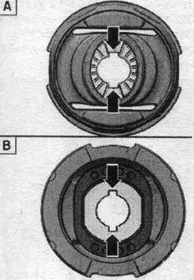
"A". Regular silent block.
"B". Hydraulic silent block.
Rear silent block
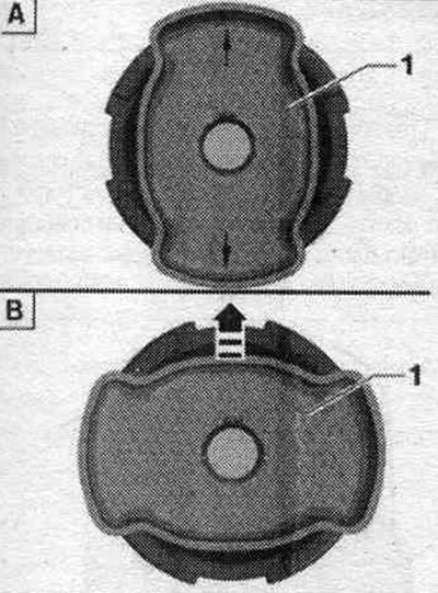
"A". Regular silent block.
"B". Hydraulic silent block.
Removal and installation the subframe with attachments
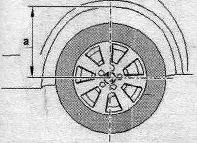
Before starting work, measure the distance "a" from the center of the wheel to the lower edge of the wheel arch while the wheels are still on the car.
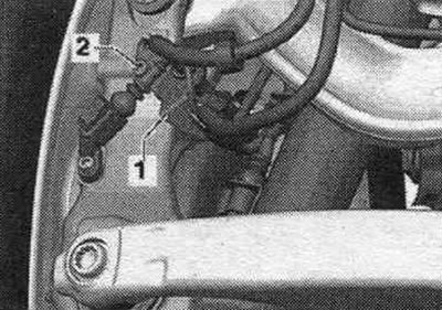
Place the car on a lift. Remove the wheels. Remove the coil springs. Remove the system resonator. exhaust. Unscrew bolt "2" on the right and left and remove bracket "1" with wires.
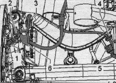
Unlock and disconnect plug connection "1" of the rear left speed sensor "G46" and the rear right speed sensor "G44". Unlock and remove connectors "3" of the right and left electronic mechanical parking brake. Disconnect plug "5" from the rear left door sensor. clearance "G76" and, if available, from the right rear. door sensor. clearance "G77" and remove it. Disconnect wiring harness "4" on the left and, if present, on the right. On vehicles with an electrical system. adjuster, damping, disconnect the connector on the bumper and release the wiring harness.
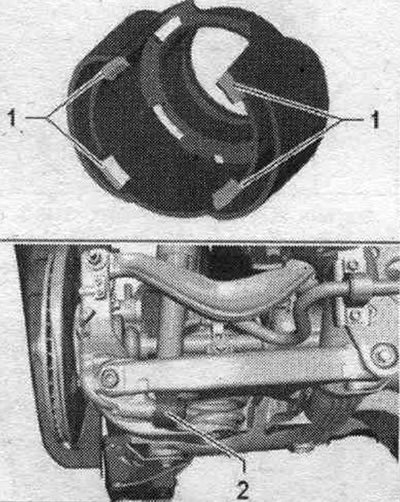
Unlock the locking tabs "1" and remove the stone protection "2".
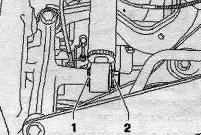
Unscrew bolt "1" and remove washer "2".
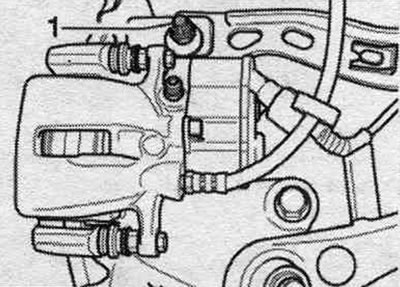
Disconnect bolt connection "1". Remove the brake caliper. Guide the caliper past the suspension elements and secure it to the body so that the weight of the caliper does not press on the brake. hoses or lines, which may damage them. Screw the upper wishbone to the hub assembly "1" by hand.
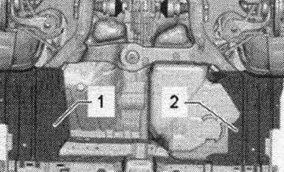
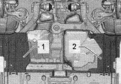
Remove cover "1" and "2".
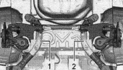
Remove stone guards "1" and "2" if present.
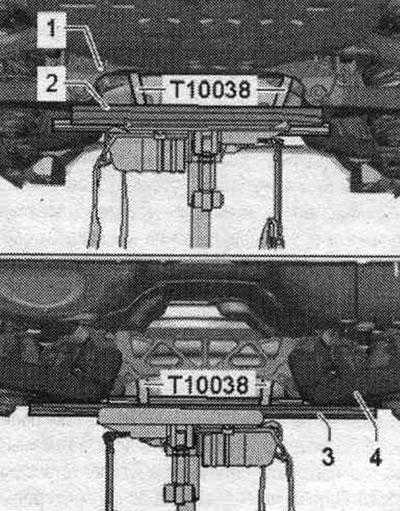
Place a tilting device with a universal mount for the "VAG1359/2" gearbox under the subframe and secure it with the "T10038" tensioning belt. Place a suitable wooden block "2" under the rear of the "1" subframe. Place a suitable wooden block "3" under the rear of the "4" subframe. Route the "T10038" tensioning belt between the subframe and the fuel tank. Route the tension belt "T10038" under the universal transmission mount "VAG 1359/2" and tighten it.
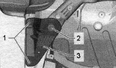
Unscrew bolts "1" and "2" on the left and right. Remove supports "3" from the left and right.
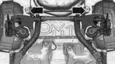
Loosen the "arrow" bolts. Carefully lower the subframe with the attached parts. At the same time, pay attention to the brakes. calipers and brakes. highways.
Installation
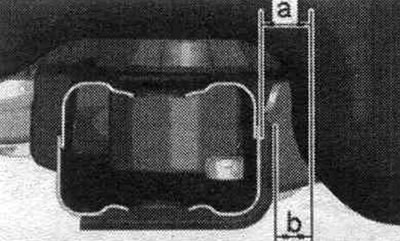
Installation in reverse order. Silent blocks have a limited torsional working range. Therefore, wheel suspension bolt connections should only be tightened when the vehicle is in the unloaded or standard suspension position. Raise the wheel support with the suspension in a static position on a vehicle with coil springs. The subframe support holes must be located in the center of the mounting points on the body. On all-wheel drive vehicles with a subframe, align the subframe so that dimension "a" for vehicles without a skid plate is 19 mm, and dimension "b" for vehicles with a skid plate is 14 mm. Install the coil springs only after the subframe bolts have been tightened to the specified torque.
Replacement of silent block and hydras, subframe silent block
If a silent block is damaged, the silent block on the opposite side should also be replaced. Before replacing a faulty silent block, inspect the remaining silent blocks. If cracks, oil stains, or other damage are present, these silent blocks should also be replaced. Depending on the model, different versions of the site-tent block are installed: standard or hydraulic. Place the car on a lift. Remove the wheels. Remove the coil springs. To replace the silent block, lower the subframe in the front or rear. areas. There is no need to remove the subframe. Lower the subframe alternately in the front or rear. area. This will avoid adjusting the wheel alignment angles. The subframe should not be lowered more than 4 cm. Before removing the silent blocks, mark their installation position relative to the subframe.
Replacing the front silent block or hydraulic silent block
Remove cover "1" and "2".
Install a powertrain lift with a universal gearbox grip "VAG 1359/2" under the subframe "1". Place a suitable block "2" under the subframe "1".
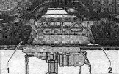
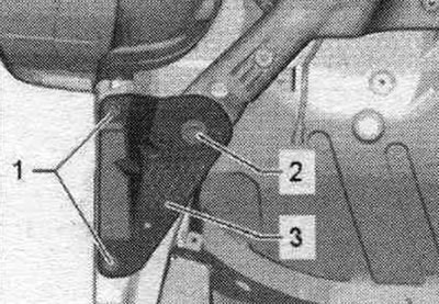
Unscrew bolts "1" and "2" on the left and right. Remove supports "3" from the left and right.
Screw the lead screw "3346/2" into the body with the mounting device "3301" and the nut "3346/3", as shown in the picture, on the opposite side of the silent block being replaced to a size of approx. 1.5 cm.
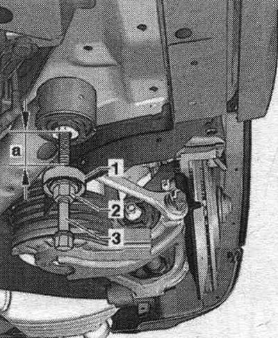
1. Mounting device "3301".
2. Nut "3346/3".
3. Lead screw "3346/2".
Screw nut "3346/3" onto lead screw "3346/2" so that dimension "a" is 4 cm. Lower the subframe only by 4 cm.
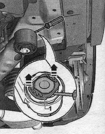
For hydraulics, silent block: Pull up the plastic insert "1", as shown in the picture
All
Mark mont. the position of the silent block or hydraulics relative to the subframe, for example, using a felt-tip pen or "arrows." The figure shows the hydraulics. silent block, on a standard silent block the grooves on the rubber rollers are rotated by 90°.
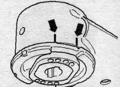
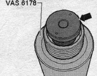
If necessary, you should unscrew the "arrow" support with the "small" inner diameter from the hydraulic. cyl. "VAS 6178", and screw in the support "T10205/13" instead.
Install the tools as shown on the front silent block.
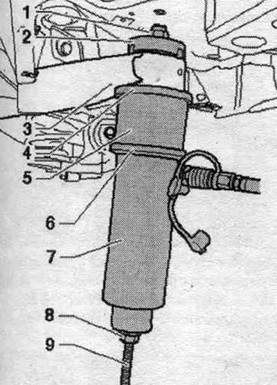
1. Nut "T10263/5".
2. Mandrel "T40185/5" groove faces the silent block.
3. Subframe.
4. Support ring "T4018 5/6".
The conical side should be facing up and the webs should fit into the holes in the silent block.
5. Pipe "T40033/3".
6. Thrust ring "T10205/4".
7. Hydraulic cylinder "VAS 6178".
8. Nut "T10263/5".
9. Lead screw "T10263/4".
The lead screw journal faces downwards.
While pressing out, hold the hydraulic cylinder "VAS 6178". The silent block is disconnected with a jerk.
Installation position of the front silent block
The arrow grooves indicate the direction of movement.
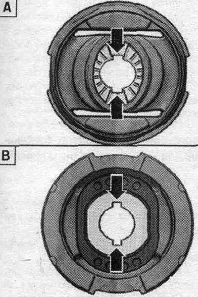
"A". Regular silent block.
"B". Hydraulic silent block.
Install the tools as shown on the front silent block.
1. Nut "T10263/5".
2. Stop "T40185/4".
3. Subframe.
4. Silent block or hydr, silent block.
5. Stop "T40185/3".
6. Thrust ring "T10205/4".
7. Hydraulic cylinder "VAS 6178".
8. Nut "T10263/5".
9. Lead screw "T10263/4".
The lead screw journal faces downwards.
Align the silent block according to the marks applied and press it in the correct position so that the flange fits against the subframe bushing without a gap. To do this, if necessary, press out and press again using a cyl. Be careful not to tilt the silent block when pressing it in, otherwise the outer ring may be damaged! The ends of the rubber tabs on the silent block must align with the previously applied "arrow" marks on the subframe. The picture shows a hydraulic silent block; on a standard silent block, the grooves on the rubber rollers are rotated by 90°.
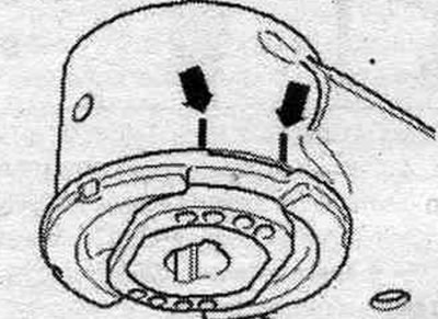
Installation in reverse order.
Replacement rear. silent block or hydr, silent block
Unscrew the nuts of both end muffler brackets up to the beginning of the threads. Install a powertrain lift with a universal gearbox grip "VAG 1359/2" under the subframe "1". Place a suitable block "2" under the subframe "1".
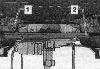
Unscrew the rear subframe bolts. Screw the lead screw "3346/2" into the body with the mounting device "3301" and the nut "3346/3", as shown in the picture, on the opposite side of the silent block being replaced to a size of approx. 1.5 cm.
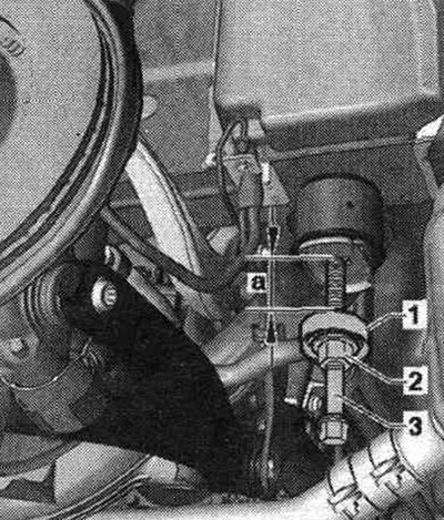
1. Mounting device "3301".
2. Nut "3346/3".
3. Lead screw "3346/2".
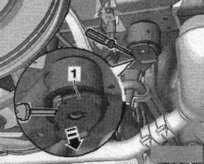
Screw nut "3346/3" onto lead screw "3346/2" so that dimension "a" is 4 cm. Lower the subframe only by 4 cm.
For hydraulics, silent blocks; Carefully press the locking device "1" against rotation with a suitable tool, for example, a screwdriver, in the area of the protrusions in several stages, alternately on each side of the hydraulics, silent block.
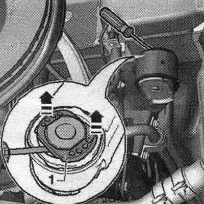
Pull out the plastic insert "1" upwards, as shown in the picture
All
Mark mont. the position of the silent block or hydraulic silent block relative to the subframe, for example, using a felt tip. "Arrows." The figure shows a hydraulic silent block. On a standard silent block, the grooves on the rubber rollers are rotated 90°. If necessary, remove the "arrow" support with the small inner diameter from the hydraulic. cyl. "VAS 6178", and screw in the support "T10205/13" instead.
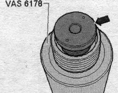
Install the tools as shown on the front silent block.
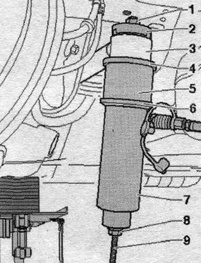
1. Nut "T10263/5".
2. Stop "T40185/5". The hole faces the silent block.
3. Subframe.
4. Support ring "T40185/6".
The conical side should be facing up and the webs should fit into the holes in the silent block.
5. Pipe "T40033/3".
6. Thrust ring "T10205/4".
7. Hydraulic cylinder "VAS 6178".
8. Nut "T10263/5".
9. Lead screw "T10263/4".
The lead screw journal faces downwards.
Rear installation position. silent block
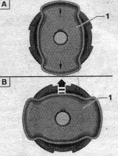
"A" standard silent block, arrows indicate direction of movement.
"B" of the hydraulic silent block, the rotation lock "1" is located across the direction of travel, the "arrow" indicates the direction of travel.
For hydraulics, silent block: Before installing the rear hydraulics, silent block, carefully press the locking device "1" against rotation with a suitable tool, for example, a screwdriver, in the area of the "arrow" protrusions in several stages, alternately on each side of the hydraulics, silent block.
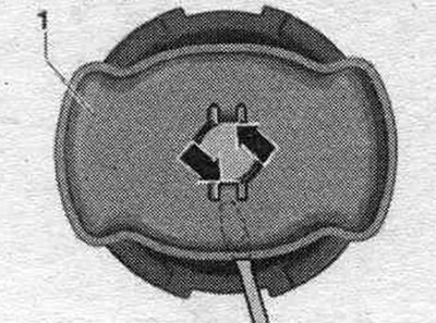
All
Install the tools as shown on the rear silent block.
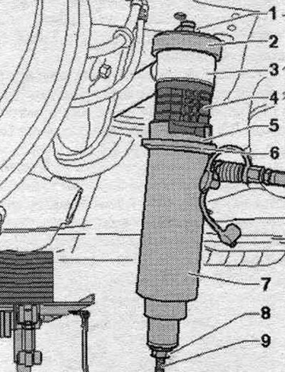
1. Nut "T10263/5".
2. Stop "T40185/4".
3. Subframe.
4. Silent block or hydr, silent block.
5. Stop "T40185/3".
6. Thrust ring "T10205/4".
7. Hydraulic cylinder "VAS 6178".
8. Nut "T10263/5".
9. Lead screw "T10263/4".
The lead screw journal faces downwards.
Align the silent block according to the marks applied and press it in the correct position so that the flange fits against the subframe bushing without a gap. To do this, if necessary, press out and press again using a cylinder. Make sure that the silent block does not become distorted at the beginning of pressing, otherwise the outer ring may be damaged. The ends of the rubber protrusions on the silent block must coincide with the previously applied "arrow" marks on the subframe. The illustration shows a hydraulic silent block. On a standard silent block, the grooves on the rubber rollers are rotated 90°. Install the anti-rotation protection on the hydraulic silent block. Installation is in reverse order..
Removing and installing the connecting rod and stabilizer
Before starting work, measure the distance "a" from the center of the wheel to the lower edge of the wheel arch while the wheels are still on the vehicle. Place the vehicle on a lift. Remove the wheels. First, unscrew bolt "4". Unscrew nut "3", remove washer "2" and bolt "1".
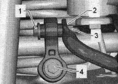
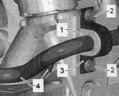
Stabilizer "4" is removed and installed complete with rubber mounts "1" and clamps "3." Do not remove the clamps or rubber mounts. Unscrew bolts "2" on the left and right and remove stabilizer "4".
Installation
Installation in reverse order. Silent blocks have a limited torsional working range. Therefore, wheel suspension bolt connections should only be tightened when the vehicle is in the unloaded or standard suspension position. Raise the wheel support with the suspension in a static position on a vehicle with coil springs. Install the stabilizer and tighten the bolts. First, tighten bolts "2" on the left and right. Then tighten bolts "2" evenly on the left and right. Insert bolt "1" with washer "2" and tighten nut "3" on the left and right. Tighten bolt "4" on the left and right. Tighten the wheel.