
Table of contents: Drive shaft with an outer CV joint… ↓ Drive shaft with an outer CV joint… ↓ Drive shaft with an outer CV joint… ↓
If the drive shaft threaded connection on the wheel side is loose, do not allow additional load to be placed on the hub bearings. If the wheel bearings are subjected to the vehicle's own weight, they may be damaged. This will reduce the service life of the wheel bearings. Therefore, it is necessary to take into account the following. It is prohibited to move the vehicle without the drive shafts installed, as this will damage the wheel hub bearing. If, however, the vehicle needs to be moved, the following must be observed. Install the outer CV joint in place of the drive shaft. Tighten the outer CV joint threads to the wheel hub to 200 Nm. During installation, do not allow the drive shaft to hang freely, as bending it will damage the inner joint.
Removal
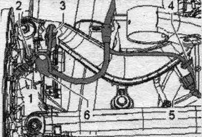
Unscrew the bolts securing the drive shaft to the wheel hub. Remove the wheel. Remove the coil spring. Remove the rear muffler of the system. exhaust pipes with brackets. Remove the rear head. transmission.
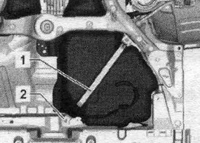
Applies to left side spar shaft only. Tighten clamp "1" again. Tighten bolt "2" only by hand.
Unlock and remove connector "5" from the left door sensor. clearance "G76". Release (if available) wiring harness "4".
All
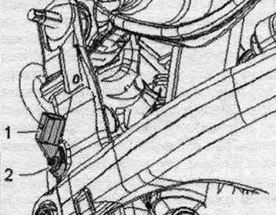
Remove the rear speed sensor "1". To do this, unscrew bolt "2". Remove the drive shafts inward.
Installation
Installation in reverse order. Install the rear ch. transmission. Install the rear. muffler system. exhaust pipes with brackets. Install the fuel pressure band clamp. tank. Install the coil spring. Install the RPM sensor at the rear. Tighten the wheel. Tighten the drive shaft to wheel hub mounting bolts.
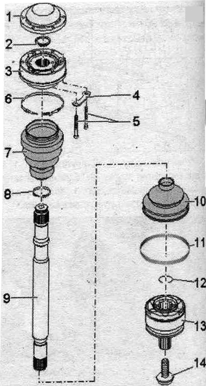
Drive shaft with an outer CV joint with a diameter of 88 mm and an inner CV joint with a diameter of 100 mm
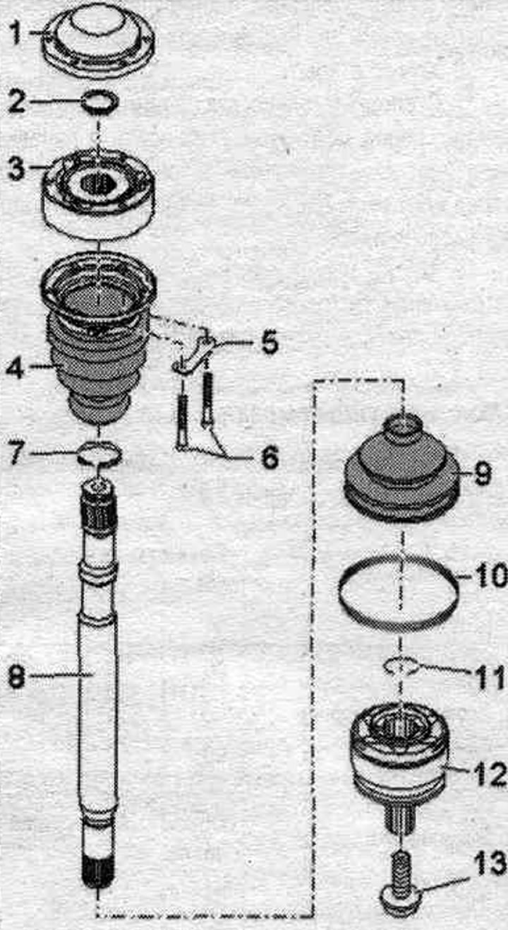
1. Lid: Carefully remove the lid using a punch; as a rule, subject to replacement; adhesive surfaces cover/inner CV joint must be degreased before installation; before installation, apply sealant to the CV joint sealing surface.
2. Retaining ring: usually needs to be replaced.
3. Inner CV joint: outer diameter: 100 mm; can only be replaced as a complete unit; adhesive surfaces cover/inner CV joint and CV joint boot/CV joint must be degreased before installation; when mounting a hinge on a profiled shaft, the teeth of the profiled shaft must be coated with a thin layer of grease used for the hinge.
4. Inner CV joint boot with cap: without ventilation hole; carefully press out the cap using a mandrel; as a rule, subject to replacement; in case of damage, check the inner CV joint; before installing on the CV joint, apply sealant to the mating surface; align the cover with the screw holes; the surfaces to be glued, the protective cover of the CV joint/CV joint, must be degreased during installation; the sealing surfaces of the joint/drive shaft boot must be degreased during installation; before tightening the clamping collar, lift the joint boot briefly to equalize the pressure.
5. Backing plate.
6. Bolt: 20 Nm + 90°; replace when removed.
7. Clamp: usually subject to replacement.
8. Drive shaft.
9. Outer CV joint boot: without ventilation hole; check for cracks and abrasions, replace if necessary; in case of damage, check the outer CV joint; the sealing surfaces of the CV joint boot/outer CV joint must be degreased during installation; the sealing surfaces of the joint/drive shaft boot must be degreased during installation; before tightening the clamping collar, lift the joint boot briefly to equalize the pressure.
10. Clamp: open.
11. Retaining ring: usually needs to be replaced; install in the shaft groove before installation (when the hinge is mounted it is not visible); before installing the CV joint, position the retaining ring joint upwards.
12. Outer CV joint: outer diameter: 88 mm; can only be replaced as a complete unit; install: using a plastic hammer, push it onto the shaft until the locking ring springs; when installing, insert the locking ring into the chamfer of the hinge; use pliers if necessary; the sealing surfaces of the CV joint boot/outer CV joint must be degreased during installation; when mounting a hinge on a profiled shaft, the teeth of the profiled shaft must be coated with a thin layer of grease used for the hinge.
13. Bolt: usually needs to be replaced; take into account the installation instructions when loosening and tightening; 200 Nm + 180°.
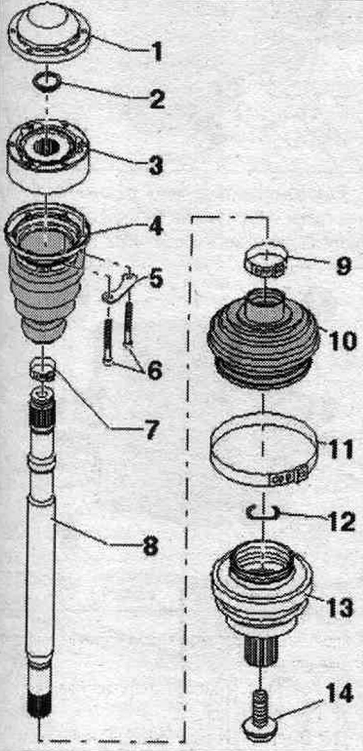
Drive shaft with an outer CV joint with a diameter of 100 mm and an inner CV joint with a diameter of 108 mm
1. Lid: Carefully remove the lid using a punch; as a rule, subject to replacement; adhesive surfaces cover/inner CV joint must be degreased before installation; before installing on the CV joint, apply sealant to the sealing surface.
2. Retaining ring: usually needs to be replaced.
3. Inner CV joint: outer diameter: 108 mm; can only be replaced as a complete unit; there should be no oil or grease on the surfaces to be glued; when mounting a hinge on a profiled shaft, the teeth of the profiled shaft must be coated with a thin layer of grease used for the hinge.
4. Backing plate.
5. Bolt: 70 Nm; replace when removed.
6. Clamp: usually subject to replacement.
7. Inner CV joint boot: without ventilation hole; in case of damage, check the inner CV joint; the sealing surfaces of the joint/drive shaft boot must be degreased during installation; before tightening the clamping collar, lift the joint boot briefly to equalize the pressure.
8. Clamp: usually subject to replacement.
9. Drive shaft.
10. Outer CV joint boot: without ventilation hole; check for cracks and abrasions, replace if necessary; in case of damage, check the outer CV joint; the sealing surfaces of the CV joint boot/outer CV joint must be degreased during installation; before tightening the clamping collar, lift the joint boot briefly to equalize the pressure.
11. Clamp.
12. Retaining ring: usually needs to be replaced; before installation, install it into the annular groove of the shaft (when the hinge is assembled it is not visible); before installing the constant velocity joint, align the retaining ring with the center of the hole by moving it upwards.
13. Outer CV joint: outer diameter: 100 mm; can only be replaced as a complete unit; install: using a plastic hammer, push it onto the shaft until the locking ring springs; when installing, insert the locking ring into the chamfer of the hinge; use pliers if necessary; the sealing surfaces of the CV joint boot/outer CV joint must be degreased during installation; when mounting a hinge on a profiled shaft, the teeth of the profiled shaft must be coated with a thin layer of grease used for the hinge
14. Bolt: usually needs to be replaced; take into account the installation instructions when loosening and tightening; 200 Nm + 180°.
Drive shaft with an outer CV joint with a diameter of 88/98 mm and an inner CV joint (with a cap) diameter 100/108 mm
1. Cover: carefully remove the cover using a mandrel, replace if damaged; adhesive surfaces cover/inner CV joint must be degreased before installation; before installing on the CV joint, apply sealant to the sealing surface.
2. Retaining ring: replace when removed.
3. Inner CV joint: can only be replaced as an assembly; there should be no oil or grease on the surfaces to be glued; when mounting a hinge on a profiled shaft, the teeth of the profiled shaft must be coated with a thin layer of grease used for the hinge.
4. Inner CV joint boot with cap: without ventilation hole; carefully remove the cap using a mandrel, replace if damaged; in case of damage, check the inner CV joint; the sealing surfaces of the cap/CV joint must be degreased during installation.
5. Backing plate.
6. Bolt: M10, 70 Nm; replace when removed.
7. Clamp: replace when removed.
8. Drive shaft.
9. Clamp: replace when removed.
10. Outer CV joint boot: without ventilation hole; check for cracks and abrasions, replace if necessary; the sealing surfaces of the joint boot/outer steel cap must be degreased during installation; the sealing surfaces of the joint/drive shaft boot must be degreased during installation.
11. Clamp: replace when removed.
12. Retaining ring: Always replace; before installation, install it into the annular groove of the shaft (when the hinge is assembled it is not visible); before installing the CV joint, align the retaining ring in the center with the hole facing up.
13. Outer CV joint: can only be replaced as an assembly: install: using a flat block or hammer, push it onto the shaft until the locking ring springs back; when installing, insert the locking ring into the chamfer of the hinge; use pliers if necessary; the sealing surfaces of the joint/outer CV joint boot must be degreased during installation; when mounting a hinge on a profiled shaft, the teeth of the profiled shaft must be coated with a thin layer of grease used for the hinge.
14. Bolt: 200 Nm + 180°; replace when removed; observe installation instructions when loosening and tightening.
Checking the inner CV joint
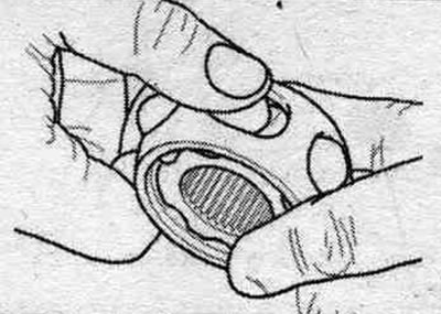
The joint must be disassembled to replace the lubricant if it is heavily contaminated, and to inspect the surfaces in contact with the balls for wear and pitting. The ball joint hub and ball joint race are matched as a pair and must be marked before removal. Do not interchange the position of the rolling tracks. Turn the clip and separator. Press the hinge in the direction of the arrow. Remove the balls from the cage.
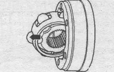
Remove the cage from the separator using the ball recesses "arrows".
Check the housing, separator, race and balls for indentations (pitting) and signs of heavy wear. Too much angular clearance in the joint is noticeable when the load changes. In such cases, the joint must be replaced. Matting of the ball surface and the presence of tracks from them are not reasons for replacing the joint.
Assembly
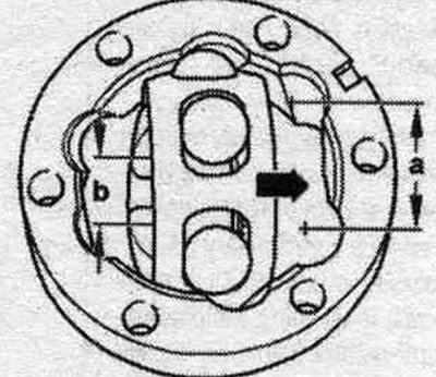
Using the 2 ball recesses, insert the cage into the separator. The mounting position is arbitrary. Install the balls into the cage. Place the hub with separator and balls on its edge in the joint cage.
When installing, ensure that after turning, the larger distance "a" on the joint collar is next to the small distance "b" on the hub. The chamfer on the inner diameter of the joint hub (splines) must face the cardan shaft.
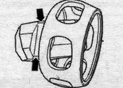
Turn the cage, to do this, remove it from the separator "arrow" so that a gap is formed between the balls and the working tracks.
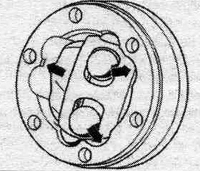
By pressing hard on the separator "arrow" turn it into the proper position together with the cage and balls.
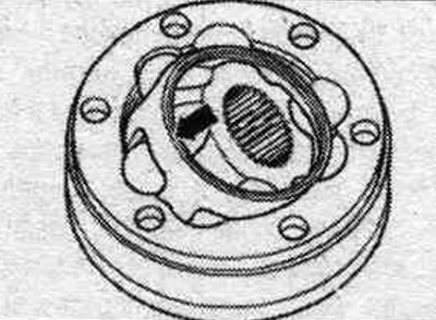
Checking the functionality of the CV joint: If the joint is assembled correctly, the cage in the housing can be freely rotated in any direction at an angle corresponding to the angle of rotation of the joint. Fill the hinge housing with a certain amount of grease.
Volumes and types of lubricants
When replacing the boot, re-lubricate the joint. Use different types of grease for the outer and inner hinges.
| Outer hinge | Lubricant volume: total volume | From this to the hinge | From this into a corrugated case |
| [mm] | [G] | [G] | [G] |
| 88 | 90 | 40 | 50 |
| Inner hinge | Apply lubricant through the ball races | ||
| 100 | 90 | ||
| Outer hinge | Lubricant volume: total volume | From this to the hinge | From this into a corrugated case |
| [mm] | [G] | [G] | [G] |
| 100 | 120 | 70 | 50 |
| Inner hinge | Apply lubricant through the ball races | ||
| 108 | 120 | ||
| Outer hinge | Lubricant volume: total volume | From this to the hinge | From this into a corrugated case |
| [mm] | [G] | [G] | [G] |
| 88/98 | 80/105 | Spread the grease evenly throughout the joint | |
| Inner hinge | |||
| 100/108 | 80/105 | Fill the joint with grease through the ball grooves | |