
Warning: Individual characteristics are also given in the text of the Chapter and, if their implementation is mandatory, are highlighted in bold.
| General parameters | |
| Clutch | |
| Type | Single disc dry with hydraulic drive |
| Maximum disc runout | 0.5 mm |
| Drive shafts | |
| Length | |
| Manual transmission (02A) and automatic transmission (096) | |
| Left drive shaft | 447.4 mm |
| Right drive shaft | 681.5 mm |
| Manual transmission (020) | |
| Left drive shaft | 455.5 mm |
| Right drive shaft | 691.5 mm |
| Position of balancing weights (measured from surface hinge to the load surface) | 524.0 - 526.0 mm |
| Lubrication of joints | |
| Type of lubricant | Grease AUDI G 000 603 |
| External ball and tripod joint | |
| Hinge AND 81 mm | |
| General | 80 g |
| Volume in the hinge | 40 g |
| Volume in protective case | 40 g |
| Hinge AND 90 mm | |
| General | 120 g |
| Volume in the hinge | 80 g |
| Volume in protective case | 40 g |
| Inner joint - ball | |
| Hinge 94mm | |
| General | 90 g |
| Volume in the hinge | 40 g |
| Volume in protective case | 50 g |
| Hinge 100mm | |
| General | 120 g |
| Volume in the hinge | 50 g |
| Volume in protective case | 70 g |
| Internal hinge - tripod | |
| General | 180 g |
| Front Hinge Volume | 90 g |
| Volume on the back side of the hinge | 90 g |
| When replacing the protective cover, supplement the hinge if necessary with grease. | |
| Tightening forces of threaded connections | |
| The tightening torques for fasteners are also given in the text of the Chapter and on
some illustrations*. *Tightening torques highlighted in bold in the text are subject to precise compliance; efforts not in bold are only approximate | |
| Clutch | |
| Clutch on the flywheel | 20 Nm |
| Clutch slave cylinder bolt | 25 Nm |
| Clutch master cylinder on pedal block | 25 Nm |
| Drive shafts | |
| Hub Nut | |
| Hub Nut | 265 Nm |
| With "plus" suspension | 200 Nm loosen by 1 revolution, tighten by 50 Nm +30° |
| Fastening the drive shaft to the gearbox flange | |
| M8 | 40 Nm |
| M10 | 80 Nm |
Driven disc and clutch basket. Engine 1.8 l
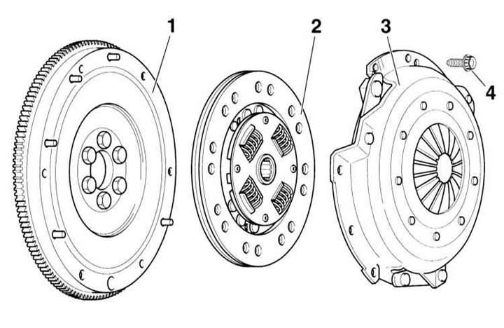
- 1 - flywheel
The contact surface with the friction linings must not contain any grease grooves. Ensure that the centering pins are securely fastened
- 2 - slave disk
Make sure the installation position is correct, the spring cage faces the pressure plate.
Warning: Clean the splines of the manual transmission input shaft, the driven disk if the old disk is installed, and the hub splines. Remove rust. Coat the splines with a thin layer of MoS2 grease. Be sure to remove excess grease.
- 3 - pressure plate
- 4 - twelve-sided bolt, 20 Nm
Loosen and tighten smoothly in a criss-cross pattern.
Note: For the version with dual mass flywheel, hexagon socket head cap screws are installed, tightening torque 13 Nm
Driven disc and clutch basket. 1.6 l engines
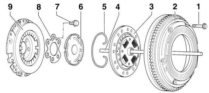
- 1 - twelve-sided bolt, 20 Nm. Loosen and tighten smoothly in a crosswise pattern.
- 2 - flywheel
The contact surface with the friction linings must not contain any lubrication grooves. Attention: The installation depth of the TDC sensor must correspond to the different sizes of flywheels. Therefore, two different color-coded threaded plugs are screwed into the clutch housing.
- 3 - driven clutch disc. Lubricate the centering elements and splines with a thin layer of MoS2 grease.
- 4 - pressure rod. Lubricate the area of the guide sleeve in the primary shaft of the manual transmission.
- 5 - retaining ring
- 6 - Clutch release disc. Lubricate the mating surface to the rod with a thin layer of MoS2 grease (VW G 000 100).
- 7 - mounting bolt. Tightening torque: 60 Nm + 1/4 turn (90°). Be sure to replace the bolts.
- 8 - intermediate plate
- 9 - pressure plate
Maximum internal deformation: 0.2 mm. A disc with damaged or loose rivets should be replaced.
Hydraulic clutch drive
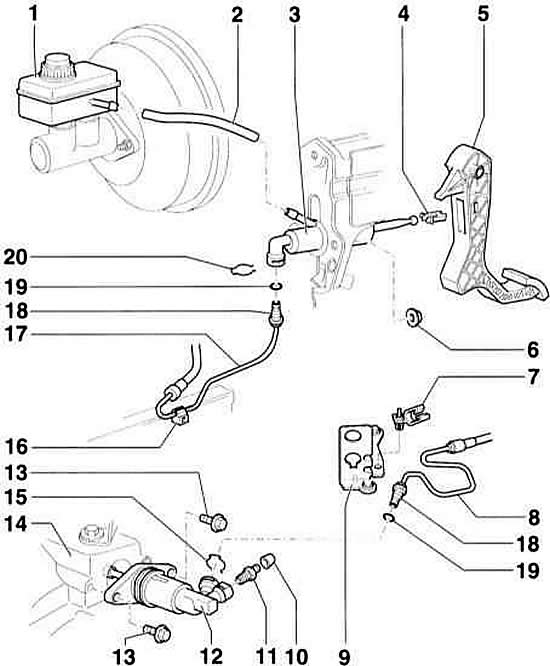
- 1 - brake fluid reservoir
- 2 - tracking hose
- 3 - master cylinder
- 4 - clamp
- 5 - clutch pedal
- 6 - nut, 25 Nm. Self-locking, be sure to replace.
- 7 - holder
- 8 - hydraulic pipeline
- 9 - support
- 10 - anther
- 11 - air bleed nipple
- 12 - working cylinder
- 13 - flange bolt, 25 Nm
- 14 - Manual transmission
- 15 - locking bracket
- 16 - clamp
- 17 - hydraulic pipeline
- 18 - connection/plug connection
- 19 - Round ring. Put it on the pipeline connection, moistening it with brake fluid
- 20 - locking bracket
When the gear is engaged, the clutch disconnects the power connection between the engine and the manual transmission and, thanks to the friction connection, ensures a smooth transfer of torque to the chassis when starting off.
The clutch consists of a pressure plate, a driven plate, a clutch release bearing and a hydraulic drive.
The pressure plate is connected to the flywheel by bolted connections. The flywheel in turn is connected to the engine crankshaft. Between the pressure plate and the flywheel there is a driven disk, which is pressed against the flywheel by the pressure plate. The driven disk is connected to the primary shaft of the manual transmission via a splined connection.
When the clutch pedal is pressed, the fluid under pressure is transferred to the slave cylinder through the master cylinder located at the bottom of the car. The piston of the slave cylinder, pressing on the clutch release bearing, acts on the pressure plate. In this case, the slave disk is moved away from the flywheel. The power connection between the engine and the manual transmission is interrupted.
The hydraulic clutch system operates on brake fluid supplied from the reservoir.
Each time the clutch is engaged and disengaged, the friction linings of the driven disk wear out as a result of the force applied. The driven disk is a fast-wearing part. However, its average service life is more than 100,000 km. The wear of the disk depends mainly on the load (operation with a trailer) and driving style. The clutch does not require maintenance, as it is self-adjusting.
Engines are usually equipped with a dual-mass flywheel. The dual-mass flywheel has a spring-damping system that helps reduce the vibrations created by the engine. In addition, this reduces the noise level in the low-speed range. The driven clutch disc in this case consists of a hub, driven plate and friction linings. There are no torsion springs.