
Table of contents: Removal ↓ Installation ↓
Constant velocity joint drive shaft
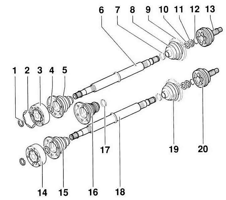
- 1 - retaining ring. Be sure to replace.
- 2 - sealing gasket. Be sure to replace. Remove the protective film and stick it to the hinge.
- 3 - internal constant velocity joint, 100 mm
- 4 - disc spring. Has teeth along the inner diameter. The large diameter is adjacent to the hinge.
- 5 - protective cover. For a constant velocity joint of 100 mm. Lubricate the inside of the cover with AUDI "D3" sealant.
- 6 - shaft. For a joint of equal angular velocities W 100 mm.
- 7 - clamp. Be sure to replace.
- 8 - protective cover. For a joint of equal angular velocities W 90 mm.
- 9 - clamp
- 10 - disc spring. Large diameter (concave side) fits against the thrust ring.
- 11 - thrust ring
- 12 - retaining ring
- 13 - outer hinge, 90 mm.
- 14 - internal hinge, 94 mm.
- 15 - protective cover. For 94 mm hinge.
- 16 - Protective cover. For 94 mm and 100 mm joint, left side only (except TDI).
- 17 - clamp
- 18 - shaft. Only for 94 mm joint.
- 19 - protective cover. For 81 mm hinge.
- 20 - outer hinge, 81 mm. Removal: with a strong blow from a light metal hammer.
Drive shaft with tripod joint. Cars with automatic transmission
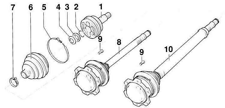
- 1 - outer hinge. Replace only as a set. Use a plastic hammer to install. Fit until the locking ring is secured.
- 2 - retaining ring. Insert into the shaft groove.
- 3 - distance ring (plastic)
- 4 - disc spring. Large ∅ (concave side) fits against the thrust ring.
- 5 - clamp. Be sure to replace.
- 6 - protective cover. For a 90 mm hinge. Before installation, lift the small clamp of the protective cover and fill the cover with air.
- 7 - clamp
- 8 - left shaft. With internal Tripode joint. If damaged, the internal joint and shaft must be replaced.
- 9 - screw with internal teeth, 45 Nm
- 10 - right hinge. With Tripod hinge. If there is any damage, the inner hinge and shaft must be replaced.
Warning: After loosening the twelve-sided nut (axle nut) that secures the drive shaft to the hub, do not place the vehicle fully loaded on the wheels or move it. Without axial compression, the wheel bearing may be damaged. If necessary, install an outer joint instead of the drive shaft and tighten it to 50 Nm.
Removal
1. Remove the decorative wheel cap; for light metal wheels, remove the caps using the removable hooks from the on-board tool kit.
2. Loosen the twelve-sided wheel hub nut at the drive shaft without removing it.
Warning: When loosening the drive shaft fastening nut, the vehicle should be parked with the wheels on the ground if possible. If the vehicle is raised, position the wrench so that the loosening force acts vertically downwards. Otherwise, the vehicle may slide off the side of the stands. High loosening torque. Risk of accident!
3. Mark the position of the corresponding front wheel relative to the hub with paint. This will allow the balanced wheel to be installed in its original position during assembly. Loosen the wheel mounting bolts with the vehicle on the ground. Raise the front of the vehicle, place it on stands, and remove the front wheel.
Warning: Lifting and installing the vehicle on stands is dangerous! Therefore, before carrying out the operation, read the subsection Jacking up a car.
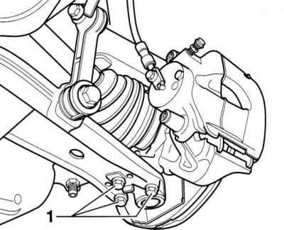
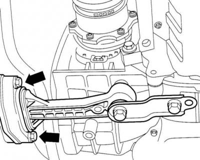
4. Mark the position of the ball joint bolts "1" with a felt-tip pen or trace them with a scriber. Otherwise, the front suspension will need to be measured and adjusted during subsequent installation. Remove bolts "1".
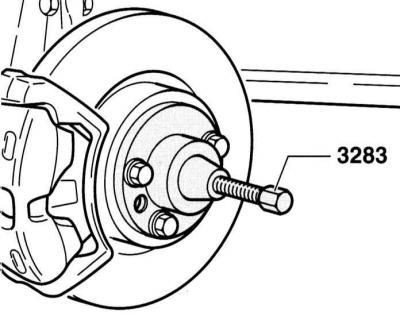
5. If the drive shaft cannot be removed from the hub manually, remove the shaft using a puller. AUDI service stations use the AUDI-3283 puller for this purpose.
Warning: Do not allow the shaft to hang, otherwise the inner joint may be damaged due to bending.
6. Remove the socket head cap screws for the drive shaft on the gearbox flange. This requires a socket head insert, such as HAZET 990 Lg-8.
7. Cars with manual transmission: Tilt the shock absorber outward and remove the drive shaft from the wheel bearing housing.
Cars with AT:
8. Loosen the mounting bolts (arrows in the illustration) aT supports to the unit beam.
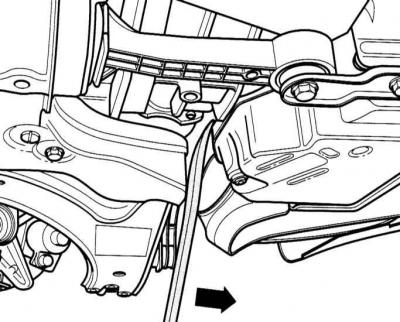
9. Insert a pry bar between the unit beam and the cylinder block and move the block in the direction of travel. At the same time, the Tripode joint of the drive shaft can be removed.
Installation
10. Brush the drive shaft teeth and threads and hub to remove rust and other contaminants.
11. Secure the shaft to the gearbox. Tighten the socket head cap screws crosswise. Gearbox tightening torque (constant velocity joint): 40 Nm; AT (tripod joint): 45 Nm.
12. Lubricate the mating surface of the twelve-point nut and the teeth of the outer joint with clean engine oil. Insert the outer joint into the teeth of the hub as far as possible.
13. Secure the ball joint to the lever. Install the mounting bolts in the oval holes so that the previously applied markings match. Tighten the bolts with a torque of 20 Nm, then tighten them with a rigid wrench to an angle of 90° (1/4 turn).
Warning: When installing in a new control arm, set the mounting bolts to the middle position and tighten. Finally, measure the camber, refer to subsection Front wheel alignment angles.
14. Install the inner drive shaft joint and tighten the socket head cap screws.
Tightening torques:
- M8 - 40 Nm
- M10 - 80 Nm
15. Cars with AT: Tighten the gearbox support mounting bolts to the unit beam to a torque of 25 Nm.
16. Insert the outer joint into the wheel bearing until it stops.
17. Tighten the twelve-sided nut to a torque of 300 Nm and then loosen it again by ½ turn.
18. Tighten the twelve-sided nut to 50 Nm, then tighten it further by 45° with a rigid wrench (1/4 turn).
Warning: To tighten to a certain angle, a HAZET 6690 angle washer is required. If such a washer is not available, the twelve-sided nut can be tightened as follows.
19. Lower the vehicle until the wheels touch the ground.
20. Tighten the twelve-sided nut to a torque of 300 Nm and then back it off by ½ turn.
21. Tighten the twelve-sided nut to a torque of 50 Nm.
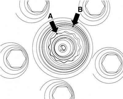
22. Mark one side of the nut (arrow A in the illustration). Place the second marking (arrow B) on the edge of the hub across the next edge. Note: The distance from one edge to the other is 45°.
23. Tighten the twelve-sided nut with a wrench until both markings match.
[The original version is on the portal: audimanual.ru]