



Table of contents: Models with manual transmission ↓ Models with automatic transmission ↓
Models with manual transmission
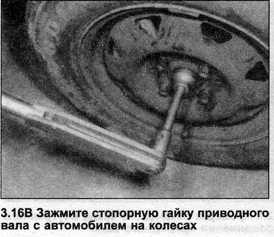
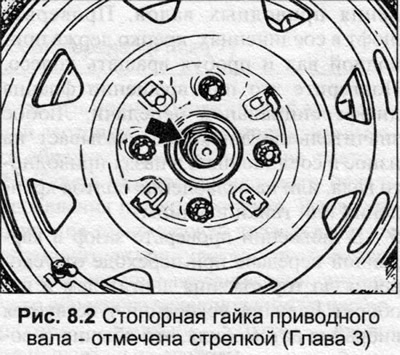
1. Remove the wheel cap, unscrew the drive shaft lock nut.
2. Loosen the four wheel mounting bolts.
3. Jack up the front of the car. Remove the wheel.
4. When working with the right drive shaft, remove the exhaust pipe and the heat-resistant shield under the inner CV joint.
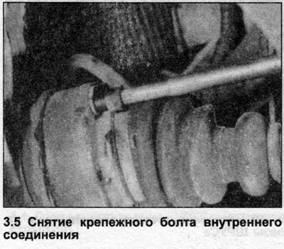
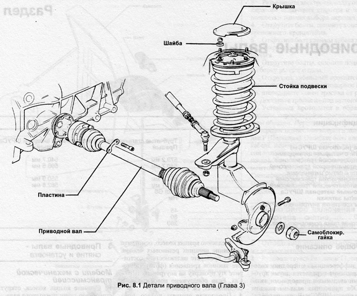
5. Unscrew the inner CV joint mounting bolts, remove the bolts with the spacer plates (photo). Separate the inner CV joint from the differential gear flange, move the drive shaft up toward the transmission.
6. Turn the steering wheel all the way to the left if you are working on the left drive shaft, or all the way to the right if you are working on the right drive shaft.
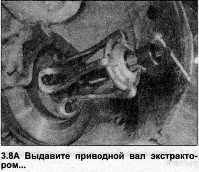
7. Apply the extractor to the front hub using the wheel mounting bolts.
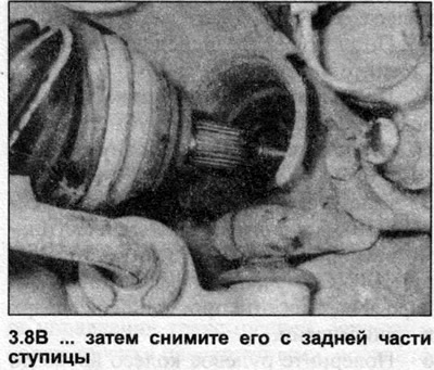
8. Press the drive shaft out of the front hub, remove the shaft assembly from under the car (photo).
Models with automatic transmission
9. Perform the actions described in points 1-4 inclusive.
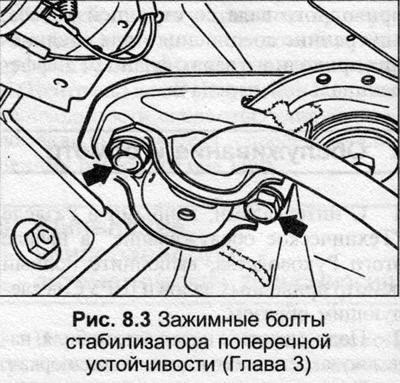
10. On the side you are working on, remove the two bolts securing the stabilizer bar clamp to the crossmember.
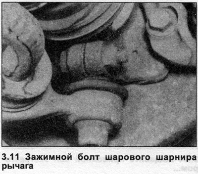
11. Unscrew the nut, remove the clamp bolt securing the ball joint of the control arm to the suspension strut. Separate the ball joint from the strut (photo).
12. Unscrew the inner CV joint mounting bolts, remove the bolts with the spacer plates. Separate the inner CV joint from the differential transmission flange.
13. Attach the extractor to the front hub with the wheel mounting bolts.
14. Press the drive shaft out of the front hub. Remove the drive shaft from under the vehicle.
All models
15. Do not move the vehicle with the drive shaft removed, as this may damage the wheel bearing.
16. Installation is carried out in reverse order, following these steps:
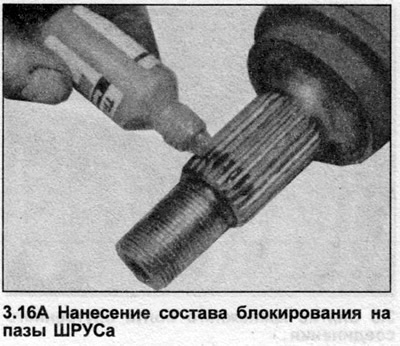
- a) The grooves and threads on the outer CV joint must be cleaned, before installing the drive shaft, apply locking compound to the grooves at the end (photo).
- b) Always use a new drive shaft lock nut, inner flange seal and, if applicable, control arm ball joint clamp bolt and nut.
- c) Tighten all nuts and bolts to the tightening torque specified in the Specifications (photo).
This article was copied from the website AUDIMANUAL