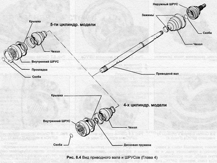
2. To remove the inner CV joint, remove the rubber boot clamps and pull the boot down the shaft away from the joint.
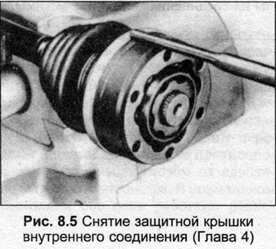
3. Knock off the protective cover from the CV joint.
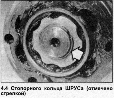
4. Remove the retaining ring at the end of the drive shaft (photo).
5. Supporting the CV joint, remove the drive shaft.
6. Remove the rubber boot and protective cover from the drive shaft, and the disc washer, if installed.
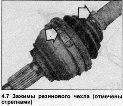
7. To remove the outer CV joint, remove the two clamps of the rubber boot, pull the boot down the shaft from the joint (photo).
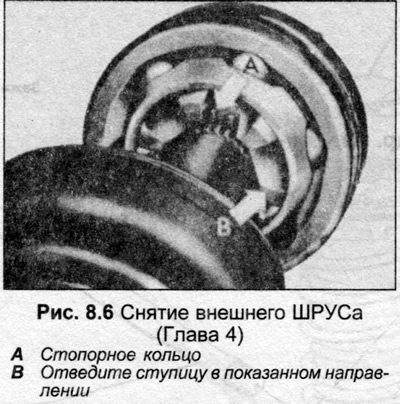
8. Remove the retaining ring and knock the connection off the shaft (Fig. 8.6).
9. Remove the rubber boot from the drive shaft.
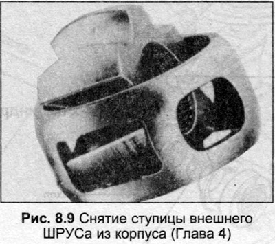
10. Before disassembling the outer joint, mark the position of the hub relative to the housing and casing.
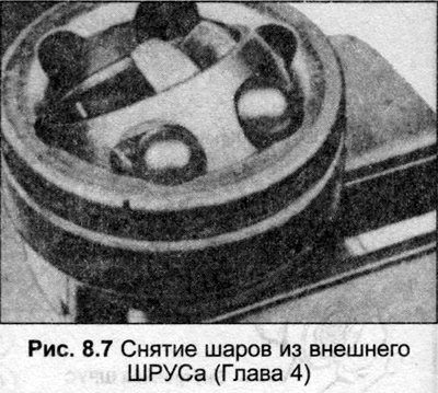
11. Turn the hub and housing and remove the balls.
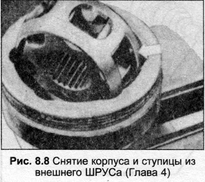
12. Rotate the housing until the two rectangular holes are aligned with the housing, remove the housing and hub.
13. Rotate the hub until one part fits into one of the rectangular holes in the housing, and turn the hub out of the housing. The parts of the joint are fitted together and individual parts cannot be replaced. If there is a large amount of play in the joint, which is felt when changing from acceleration to engine braking, or vice versa, replace the joint.
14. When reassembling the joint, wash off all old grease, use a new retaining ring, rubber boot and clamps. Use only the special lubricant recommended by Audi - see Specifications.
15. Squeeze half a portion of grease (45 g) into the joint, install the housing and hub into the casing.
16. Insert the balls into the hub.
17. Install the new retaining ring into the hub groove, squeeze the remaining grease into the joint so that the total amount is 90 g.
18. The internal connection is disassembled in a similar manner. Turn the hub and housing, push them out of the casing (Fig. 8.10).

19. Remove the balls, align the two grooves, remove the hub from the housing.
20. When assembling, squeeze half of the grease out of each side of the joint. On 4-cylinder models, the total amount of grease injected into each internal joint is 90 g, on 5-cylinder models, 120 g.
21. It is recommended to install new rubber boots on the shaft. Install the boots, inject the remaining grease into the boots.
22. Install the Belleville washer, where applicable, onto the inner end of the drive shaft, position the protective cap on the boot. Note that the concave side of the Belleville washer must face the joint.
23. Place the inner joint on the shaft and secure it with a new retaining ring.
24. Place the protective cover on the outside.
25. Place the outer joint against the end of the drive shaft and use a mallet to tap it onto the shaft, securing it with a new retaining ring.
26. Install new clamps on the ends of the rubber boots, position the boots on the connections, and squeeze the clamps.