
Repair Chevrolet Repair Toyota Repair Honda Repair AvtoVAZ Repair Mercedes-Benz Repair BMW Repair Opel
Home  |  Contacts  |  Sitemap  |    
English Русский
Български
Беларускі
Український
Српски
Hrvatski
Română
Polski
Slovenský
Magyar
AudiManual.ru


  • AUDI 80
  • AUDI 100
  • AUDI A3
  • AUDI A4
  • AUDI A6
  • AUDI A8
  • AUDI Q
  • OTHER
  • ARTICLES
B8 (2007-2015) B7 (2004-2008) B6 (2000-2006) B6 (2000-2006, petrol) B5 (1994-2001) B5 (1994-2001, petrol)

Spring strut with upper support, shock absorber fork, upper control arm, tension rod (Audi A4 B8)

  • Home
  • Audi A4
  • B8 (2007-2015)
  • Chassis
  • Front suspension
  • Spring strut with upper support, shock absorber fork, upper control arm, tension rod
            0
Table of contents: Removal and installation the spring… ↓ Removal and installation the shock… ↓ Removal and installation the upper… ↓ Removal and installation the… ↓
Spring suspension strut with upper support, shock absorber fork, upper control arm, tension rod.
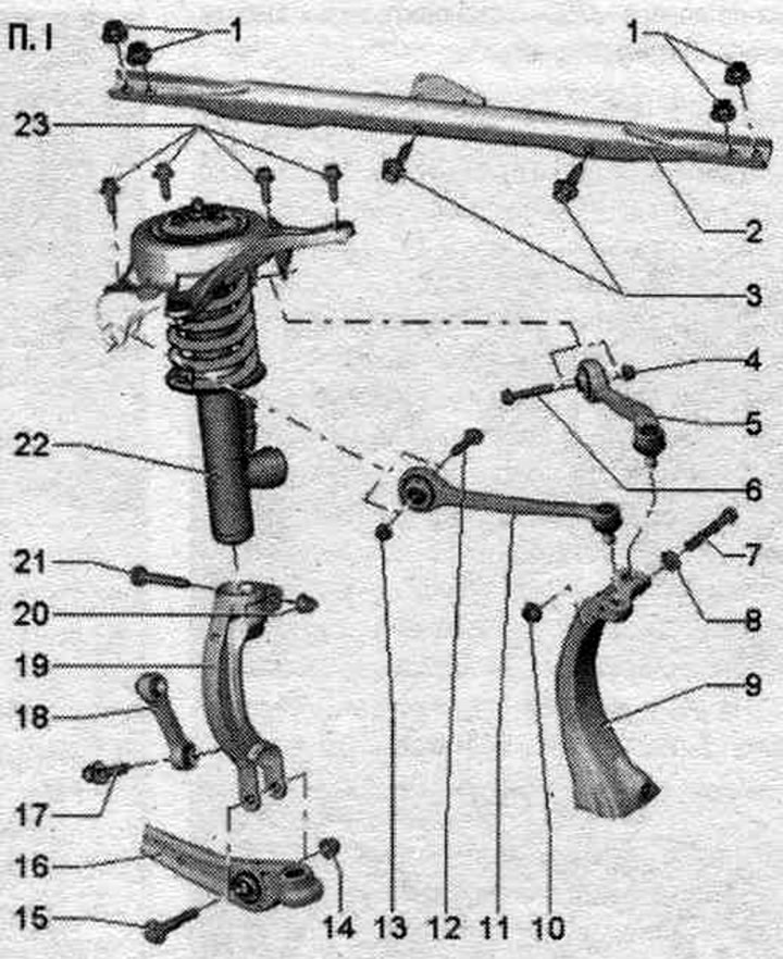
1. Nuts: 30 Nm.

1. Nuts: 30 Nm.
2. Stretching.
3. Bolts: 7 Nm.
4. Nut: Replace when removed.
5. Suspension arm at the top rear.
6. Bolt: 50 Nm + 90°; replace when removed; tighten only when the vehicle is in a no-load position.
7. Bolt: Replace when removed.
8. Washer.
9. Hub bearing housing.
10. Nut: 40 Nm; replace when removed.
11. Upper front suspension arm.
12. Bolt: 50 Nm + 90°; replace when removed; tighten only when the vehicle is in a no-load position.
13. Nut: Replace when removed.
14. Nut: 90 Nm + 90°; replace when removed; tighten only when the vehicle is in a no-load position.
15. Bolt: replace when removed.
16. Carrying lever.
17. Bolt: 40 Nm + 90°; replace when removed; tighten only when the vehicle is in a no-load position.
18. Connecting rod: take into account installation. position; take into account different designs: aluminum and steel; simultaneous installation of 2 racks of different types is not allowed.
19. Shock absorber fork.
20. Nut: 40 Nm +1 80°; replace when removed.
21. Bolt: Replace when removed.
22. Shock absorber strut: it is necessary to take into account differences in the design of the chassis, see the vehicle data plate; before disposing of faulty shock absorbers, carefully remove gas and oil from them.
23. Bolts: 40 Nm + 90°; observe the sequence, tighten, replace when removing.


Removal and installation the spring strut with the upper support


Remove the wheel. Tie the wheel bearing housing as shown in the figure using the tension belt "T10038".
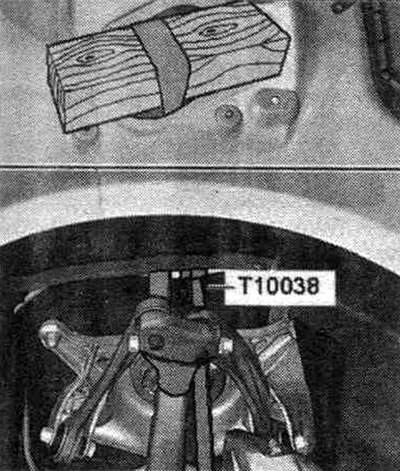
Remove the wheel. Tie the wheel bearing housing as shown in the figure using the tension belt…


Only cars with electric system. damping adjustment: Unlock and remove connector "3". Remove fasteners "1" and "2".
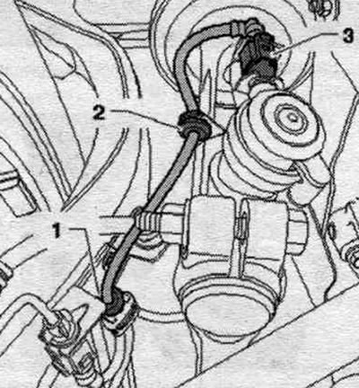
Only cars with electric system. damping adjustment: Unlock and remove connector «3». Remove…


All


Remove the shock absorber fork. Disconnect bolt connection "1". Remove both upper suspension arm pivot pins "2" from the hub bearing housing. Flaring of splines in the hub bearing housing using a chisel, etc. is not permitted!
Remove the shock absorber fork. Disconnect bolt connection «1». Remove both upper suspension arm…


Left side of the vehicle: Unlock and remove the water drainage channel cover "3".
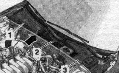


Left side of the vehicle: Unlock and remove the water drainage channel cover «3».


Unscrew nut "1". Remove filler neck "3" with feed tube from windshield washer reservoir and body opening "arrow B".
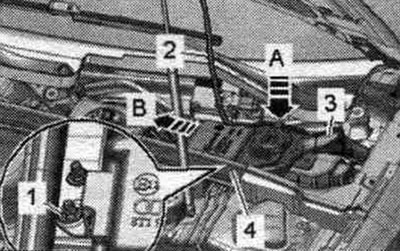
Unscrew nut «1». Remove filler neck «3» with feed tube from windshield washer reservoir and body…


Unscrew the arrow bolts and remove the cover of the left switching unit.

Unscrew the arrow bolts and remove the cover of the left switching unit.


Unscrew the "arrow" nuts, remove the coolant reservoir upwards and put it aside.
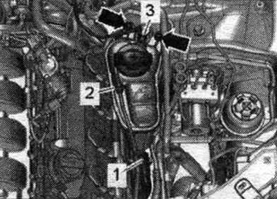
Unscrew the «arrow» nuts, remove the coolant reservoir upwards and put it aside.


Right side of the vehicle: Unlock and remove the water drainage channel cover "1".


All


Unscrew the arrow bolts and remove the spring suspension strut with the upper support.
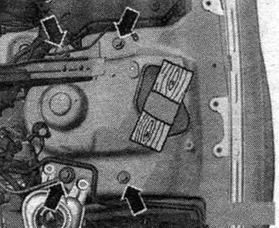
Unscrew the arrow bolts and remove the spring suspension strut with the upper support.


Installation


Installation in reverse order. Install and tighten the given bolts in the following order. "1, 2, 3" and "4". Observe the sequence of tightening the bolted connections of the support bracket with the shock absorber strut on the cup.
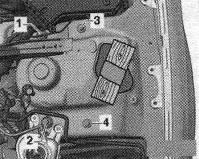
Installation in reverse order. Install and tighten the given bolts in the following order. «1, 2,…


When tightening, press the upper arm as far down as possible! Tighten bolt connection "1".
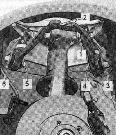
When tightening, press the upper arm as far down as possible! Tighten bolt connection «1».


When installing, make sure that the T-shaped pin "arrow" is fixed in the groove of the shock absorber fork. Silent blocks have a limited working range of twisting. Therefore, wheel suspension bolt connections should only be tightened when the vehicle is in the unloaded or standard suspension position.
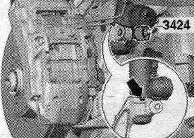


When installing, make sure that the T-shaped pin «arrow» is fixed in the groove of the shock…


Raise the wheel support to the unloaded suspension position. For vehicles with automatic headlight range control, perform basic headlight installation. After removing and installing the door sensor. clearance or detachment of rods on vehicles with an electric system. reg, the damping adjustment position should be readjusted. If the control position is re-adapted on a vehicle with lane departure warning, the lane departure warning control unit "J759" must be recalibrated. Install the shock absorber fork. Tighten the wheel.

Removal and installation the shock absorber fork


Remove the wheel. Unscrew nut "1" and remove casing "2". Remove sound insulation.
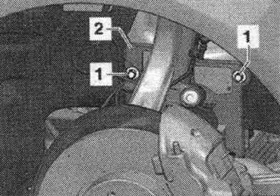
Remove the wheel. Unscrew nut «1» and remove casing «2». Remove sound insulation.


On a car with a road sensor. unscrew nut "2" from the clearance. Disconnect bolt connection "2".
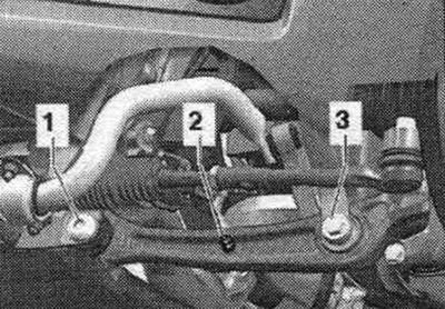


On a car with a road sensor. unscrew nut «2» from the clearance. Disconnect bolt connection «2».


Disconnect bolted connections "1" and "3". Remove connecting rod "2".
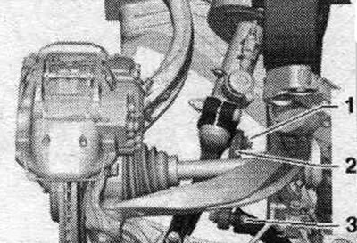
Disconnect bolted connections «1» and «3». Remove connecting rod «2».


Unscrew nut "1" of the cross steering wheel tip pin. rod "2" until it is flush with the thread of the finger. When loosening, if necessary, hold it from turning. To protect the threads, leave the nut on the pin screwed on for a few turns.
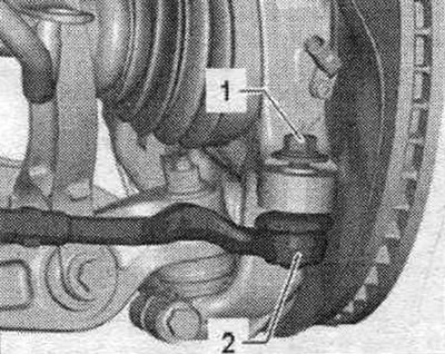
Unscrew nut «1» of the cross steering wheel tip pin. rod «2» until it is flush with the thread of…


Press out the crossbar tip. remove the rods from the hub bearing housing using the T40010 A ball joint puller. Then unscrew the nut.
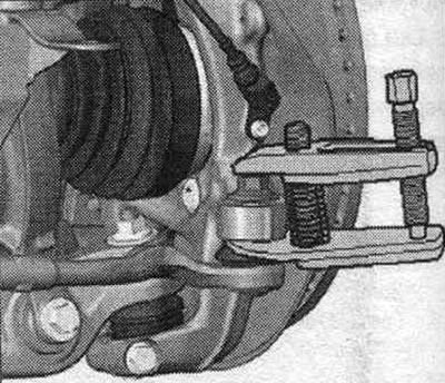


Press out the crossbar tip. remove the rods from the hub bearing housing using the T40010 A ball…


Disconnect bolted connection "3". Disconnect threaded connection "1", remove the support arm and tilt it forward. To remove bolt "1", depending on the side of the car, turn the steering wheel. mechanism all the way to the left or right. Disconnect bolt connection "1".
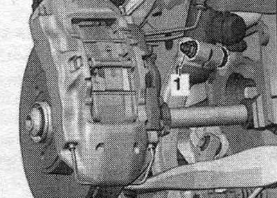
Disconnect bolted connection «3». Disconnect threaded connection «1», remove the support arm and…


Insert the rectifier "3424" into the spline of the wheel bearing housing. Rotate the ratchet 90° and remove it from the rectifier "3424". Pull the shock absorber fork "1" downwards from the shock absorber tube and remove it.
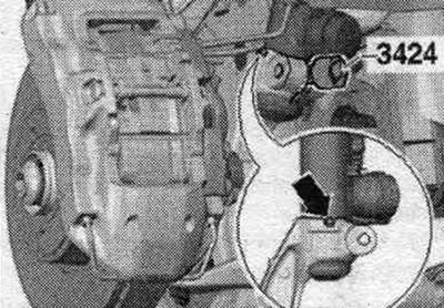
Insert the rectifier «3424» into the spline of the wheel bearing housing. Rotate the ratchet 90°…


Installation


Installation in reverse order. When installing, please ensure that:. so that the T-shaped pin "arrow" is fixed in the groove of the shock absorber fork. Silent blocks have a limited working range of twisting. Therefore, wheel suspension bolt connections should only be tightened when the vehicle is in the unloaded or standard suspension position. Raise the wheel support to the unloaded suspension position. For vehicles with automatic headlight range control, perform basic headlight installation. After removing and installing the door sensor. clearance or detachment of rods on vehicles with an electric system. reg, the damping adjustment position should be readjusted. If the steering position is re-adapted on a vehicle with lane assist, the lane assist control unit "J759" must be recalibrated. Tighten the wheel.


Removal and installation the upper control arm


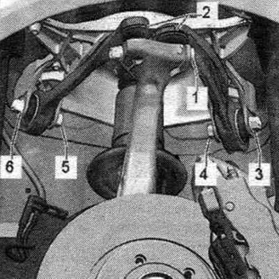
Remove the wheel. Disconnect bolt connection "1". Remove both upper suspension arm pivot pins "2" from the hub bearing housing. Flaring the splines in the hub bearing housing using a chisel or the like is not permitted! Loosen nuts "3" and "6." Remove bolts "4" and "5" and remove the upper control arm.

Remove the wheel. Disconnect bolt connection «1». Remove both upper suspension arm pivot pins «2»…


Installation


Installation in reverse order. Silent blocks have a limited torsional working range. Therefore, wheel suspension bolt connections should only be tightened when the vehicle is in the unloaded or standard suspension position. Install the upper control arm and insert bolts "4" and "5". Screw on nuts "3" and "6" and tighten them by hand. Insert both upper control arm pivot pins "2" into the hub bearing housing and insert bolt "1." When tightening, press the upper control arm down as far as possible! Tighten bolt connection "1." Raise the wheel support to the unloaded suspension position. When tightening nuts "3" and "6," the upper control arms of the suspension must be pressed toward the inside of the car. Tighten nuts "3" and "6." Tighten the wheel.

Removal and installation the stretcher


Unlock and remove the casing of the water drainage box "1" and "3".
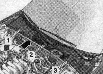
Unlock and remove the casing of the water drainage box «1» and «3».


Unscrew bolt "1" and remove the switching block in the "direction of the arrow" from the brace.
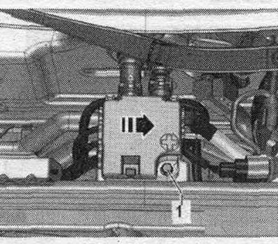
Unscrew bolt «1» and remove the switching block in the «direction of the arrow» from the brace.


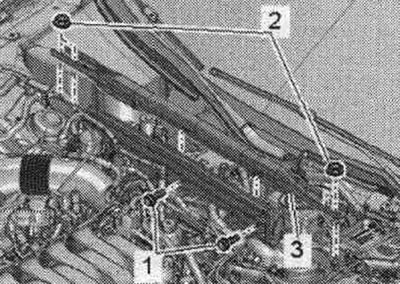
Unscrew bolts "1" and nuts "2" and remove stretcher "3".
Unscrew bolts «1» and nuts «2» and remove stretcher «3».


Installation


Installation in reverse order.

Material republished from the website audimanual.ru
The article was checked by auto expert Timur Bazhenov
This article is available at russian, bulgarian, belarusian, ukrainian, serbian, croatian, romanian, polish, slovak, hungarian

Share information:
Previous articles
Audi A4 B8: Front suspension
Next articles

Electronic damping control system
Subframe, crosspiece, stabilizer, connecting rod, subframe shield
Support arm, ball joint, guide arm, vehicle level sensor
Wheel bearing housing, hub unit
Drive shaft
AAR 2600i or 3300i forged tripod joint — disassembly and assembly


Similar articles on other Audi car models:
Rear suspension strut / shock absorber — removal and installation Audi 80 B3 (1986-1991, petrol)
Rear suspension strut/shock absorber — removal and installation Audi 100 C3 (1982-1990, diesel)
Disassembling the shock absorber / removing and installing the… Audi A3 Type 8L (1996-2003)
Unscrewing the upper shock absorber mount Audi A6 C5 (1997-2004)
Shock absorber strut Audi A8 D2 (1994-2002)
Spring strut with upper support, shock absorber fork, upper… Audi Q5 Type 8R (2008-2017)
Removal and installation the upper trim of the A-pillar Audi A2 (1999-2005)
Link to this page in different formats


Visitor comments

No comments yet


How much will 38 + 16 =


A4(B8, 2007-2015) 
  • General information
  • Operating instructions
  • Power unit
  • Petrol engines 1.8 l
  • Petrol engines 1.8/2.0 l
  • Petrol engines 3.0 l
  • Petrol engines 3.2 l
  • Fuel system (petrol)
  • Diesel engines 2.0 l (CA*)
  • Diesel engines 2.0 l (CJCB)
  • Diesel engines 2.7/3.0 l
  • Diesel engines 3.0 l
  • Fuel system (diesel)
  • Transmission
  • Manual gearbox 0B1
  • Manual gearbox 0B2
  • Manual gearbox 0B3
  • Manual gearbox 0B4
  • Automatic transmission 0B5
  • Automatic transmission 0B6
  • Automatic transmission 0AW
  • All-wheel drive system
  • Chassis
  • Front suspension
  • Rear suspension
  • Brake system
  • Steering system
  • Body
  • Exterior
  • Interior
  • Seats
  • Doors, locks and windows
  • Security system
  • Heating and air conditioning
  • Electrical equipment
  • Audio system
  • Power devices
  • Equipment and devices
  • Lighting and lamps
  • Electrical circuits
 
A4(B7, 2004-2008) 
  • General information
  • Introduction to manual
  • Troubleshooting
  • Operating instructions
  • Maintenance
  • Power unit
  • Petrol engines 2.0 (ALT)
  • Petrol engines 2.0 (TFSI)
  • Petrol engines 1.8 (MPI)
  • Diesel engines
  • Cooling system
  • Air conditioner
  • Fuel and exhaust system
  • Ignition system
  • Starting and charging
  • Transmission
  • Clutch
  • Manual gearbox
  • Automatic gearbox
  • Drive shafts
  • Chassis
  • Brake system
  • Front suspension
  • Rear suspension
  • Steering
  • Body
  • Exterior
  • Interior
  • Electrical equipment
  • Equipment and devices
  • Lighting and signaling
  • Windscreen wipers and washers
  • Electrical diagrams
  • Electrical diagrams (since 2007)
 
A4(B6, 2000-2006) 
  • General information
  • Vehicle Description
  • User manual
  • Maintenance
  • Power unit
  • Gasoline engine
  • Diesel engine
  • Lubrication system
  • Cooling system
  • Supply system
  • Injection system
  • Exhaust system
  • Ignition and control
  • Transmission
  • Gear box
  • Clutch and drive shafts
  • Chassis
  • Brake system
  • Car suspension
  • Steering
  • Body
  • Heating and ventilation
  • Exterior (external elements)
  • Interior (internal elements)
  • Electrical equipment
  • Power devices
  • Lighting and appliances
  • Electrical circuits
 
A4(B6, 2000-2006, petrol) 
  • General information
  • Introduction to the guide
  • Car care
  • Power unit
  • Engine repair
  • Lubrication system
  • Cooling system
  • Injection and control system
  • Ignition system
  • Power and exhaust system
  • Transmission
  • Clutch and drive shafts
  • Car gearbox
  • Chassis
  • Suspension and wheels
  • Steering
  • Brake system
  • Body
  • Interior
  • Exterior
  • Electrical equipment
  • Equipment and devices
  • Lighting and signaling
  • Power devices
  • Electrical circuits
 
A4(B5, 1994-2001) 
  • General information
  • Introduction to the guide
  • Car care
  • Maintenance (gasoline)
  • Maintenance (diesel)
  • Power unit
  • Gasoline engines
  • Diesel engines
  • Engine overhaul
  • Cooling system
  • Fuel injection (gasoline)
  • Fuel system (diesel)
  • Exhaust system
  • Ignition system
  • Transmission
  • Clutch
  • Mechanical gearbox
  • Automatic gearbox
  • Drive shafts
  • Chassis
  • Brake system
  • Car suspension
  • Steering
  • Body
  • Exterior
  • Interior
  • Doors, locks and windows
  • Heating and ventilation
  • Electrical equipment
  • Power devices
  • Equipment and devices
  • Electrical circuits
 
A4(B5, 1994-2001, petrol) 
  • General information
  • Vehicle description
  • Maintenance
  • Power unit
  • Engine repair
  • Turbocharging
  • Exhaust system
  • Cooling system
  • Ignition system
  • Fuel system
  • Motronic injection system
  • MPI and MPFI injection system
  • Transmission
  • Clutch
  • Gearbox and shafts
  • Chassis
  • Steering
  • Car suspension
  • Brake system
  • Wheels and tires
  • Body
  • Heating and ventilation
  • Body parts
  • Electrical equipment
  • Fuses and relays
  • Power devices
  • Lighting and lamps
  • Tools and devices
  • Electrical circuits
 
AudiManual.ru © 2017-2026 · Mobile version · Feedback · Sitemap: EN BG BY UA RS HR RO PL SK HU · Site search · News and articles
80 B2 · 80 B3 petrol · 80 B3 · 80 B4 · 100 C3 diesel · 100 C3 petrol · 100 C3 · 100 C4 petrol · 100 C4 · A3 Type 8L · A4 B5 petrol · A4 B5 · A4 B6 petrol · A4 B6 · A4 B7 · A4 B8 · A6 C4 · A6 C5 · A6 C5 Allroad · A8 D2 · Q5 Type 8R · Q7 Typ 4L · Audi A2 ·
This site uses cookies 🍪. Click the button to accept this fact.