
Disassembly and assembly of the AAR 2600i or 3300i hammered tripod joint
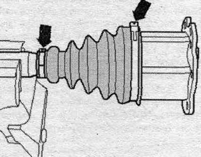
Clamp the drive shaft in a vice in a horizontal position. Use soft inserts in the vice. Make sure that the drive shaft is not damaged. Mark the position of the hinge part relative to the drive shaft. If they are not marked and installed in the wrong place during assembly, noise may occur later during operation. A waterproof marker is suitable for making marks. Open the "arrow" clamps. Move the joint boot back.
Volumes and types of lubricant
When replacing the boot, re-lubricate the joint. Use different types of grease for the outer and inner hinges.
| Outer hinge diameter, mm | Lubricant: total volume [g] | From this to the hinge [g] | From this into a corrugated case [g] |
| 85/88 | 128/90 | 64/50 | 60/40 |
| 94/100 | 194/140 | 100/80 | 94/60 |
| 99/106 | 280 | 100 | 180 |
| Inner hinge | 160 | 80 | 80 |
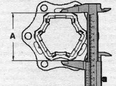
Differences between the AAR 2600i and AAR 3300i drive shafts
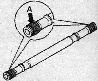
Determine the size "A" as shown in the picture Dimension "A" 74 mm = AAR 2600i drive shaft. Dimension "A" 77 mm = AAR 3300i drive shaft. Ensure the correct tool is used for each drive shaft.
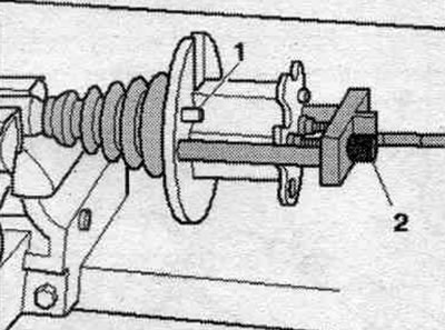
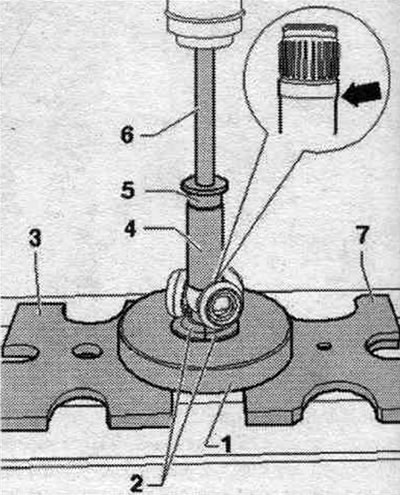
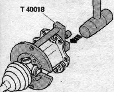
Insert the T40018 assembly tool for the AAR 3300i tripod joint or the T40084 assembly tool for the AAR 2600i tripod joint behind the hinge element. Guide pin "1" must be flush with the outside of the hinge portion. Turn the knurled head screws "2" until the assembly tool touches the hinge part. The hinge element must be secured in the "T40018" or "T40084" assembly tool without any play. Tighten bolts "2" by hand only.
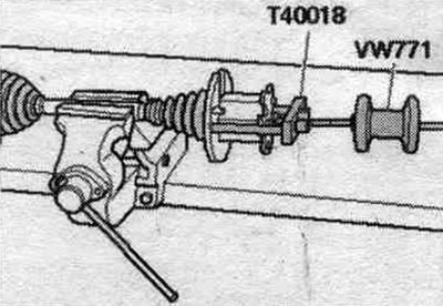
Screw the VW 771 assembly tool into the T40018 or T40084 assembly tool. The illustration shows the T40018 assembly tool for the AAR 3300i drive shaft. For the AAR 2600i drive shaft, use the T40084 assembly tool. Using an impact driver, remove the hinge portion horizontally. Leave the hinge element in the assembly tool "T40018" or "T40084".
Mark the installation positions of parts "1" and "2" with dashes. If they are not marked and installed in the wrong positions during assembly, noise may occur later during operation. A waterproof marker is suitable for making marks.
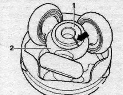
1. Drive shaft.
2. Tripod joint sprocket.
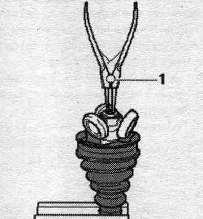
Remove grease with a clean cloth. Remove the retaining ring.
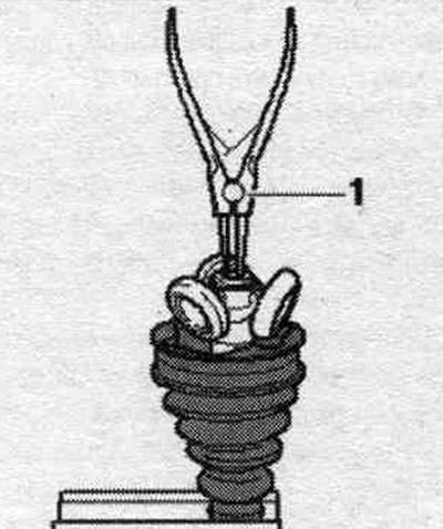
1. Ticks (common).
Press the tripod joint sprocket off the drive shaft. Use the ones shown in the picture special tools.
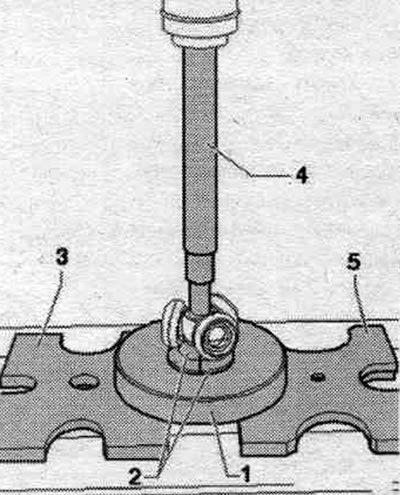
1. Mounting device "T10065/1".
2. The mounting device "T10065/5" must fit snugly against the tripod joint sprocket.
3. Pressure plate "VW 401".
4. Mandrel "VW 408 A".
5. Pressure plate "VW 402".
The mounting device "T10065/5" "2" must not touch the rolling elements of the bearing or move them to the sides. Remove the hinge boot. Remove grease from the shaft teeth. Check the wear of the rolling element and guide. Clean the drive shaft and housing.
Assembly
Slide the small terminal clamp with the hinge cover on and set the hinge cover to the position depending on the version.
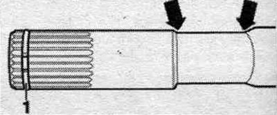
Design with marking groove: Position the joint boot in the outer groove "arrow B". The inner groove "arrow A" must not be covered by the "control groove" (to determine the correct installation of the hinge boot).
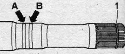
Version with deep groove: Position the joint boot between the "arrows".
Press the tripod joint sprocket onto the drive shaft: The chamfer on the tripod joint sprocket faces the drive shaft and is designed to facilitate installation. Before installing the tripod joint hinge or sprocket, the "A" teeth must be coated with a thin layer of the same grease used for the hinge. Install the tripod joint sprocket onto the shaft in accordance with the mark and push it in until it stops.
Use mont. device "T10065/6" "2", while making sure that it engages with the drive shaft at the bottom by the thickening "arrow". Use the ones shown in the figure special tools.
1. Mounting device "T10065/1".
2. The mounting device "T10065/6" must engage from below with the "arrow" thickening of the drive shaft.
3. Pressure plate "VW 401".
4. Tubular insert "VW 416 B".
5. Thrust washer "VW 447 H".
6. Mandrel "VW 411".
7. Pressure plate "VW 402".
The mounting device "T10065/6" "2" must not touch the rolling elements of the bearing or move them to the side. Press the tripod joint sprocket onto the drive shaft. Install the retaining ring. The locking ring should lock into place with an audible click, and the sprocket should fit snugly against the locking ring without any gap.
1. Ticks (common).
Enter from the back. sides of the tripod joint approx. 60% drive shaft grease from the repair kit. Lightly lubricate the rolling elements with grease. Make sure the rolling elements are not warped! Using a flat block or hammer, press the joint collar onto the tripod sprocket. The illustration shows the T40018 assembly tool for the AAR 3300i drive shaft. Inject any remaining grease into the joint boot. Ensure that the boot is correctly positioned on the joint. The boot must fit into the groove and around the perimeter of the hinge housing.
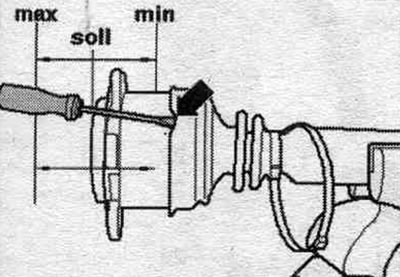
Set the hinge element to the middle position. See min/max position. When setting the joint to the middle position, release air from the joint boot, for example, using an arrow-shaped screwdriver.
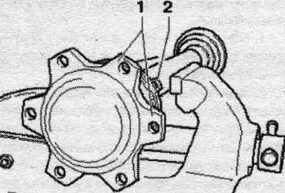
Install the clamp. To make it easier to install the internal gear head cap screws when mounting the drive shaft, it is necessary that the eye "2" of the clamp is located between the mounting flanges "1" of the hinge part. Crimp the clamping straps onto the tripod joint.
(The original article is available on the website: «AUDIMANUAL.RU»)