Repair Chevrolet Repair Toyota Repair Honda Repair AvtoVAZ Repair Mercedes-Benz Repair BMW Repair Opel
Home  |  Contacts  |  Sitemap  |    
English Русский
Български
Беларускі
Український
Српски
Hrvatski
Română
Polski
Slovenský
Magyar
AudiManual.ru


  • AUDI 80
  • AUDI 100
  • AUDI A3
  • AUDI A4
  • AUDI A6
  • AUDI A8
  • AUDI Q
  • OTHER
  • ARTICLES
B8 (2007-2015) B7 (2004-2008) B6 (2000-2006) B6 (2000-2006, petrol) B5 (1994-2001) B5 (1994-2001, petrol)

Tire pressure sensor — removal and installation (Audi A4 B8)

  • Home
  • Audi A4
  • B8 (2007-2015)
  • Chassis
  • Front suspension
  • Tire pressure sensor — removal and installation
            0
Table of contents: Tire pressure sensor ↓ Removal and installation the tire… ↓

Tire pressure sensor


1. Front left wheel pressure sensor «6222», front right wheel «G223», rear left wheel «G224» or…

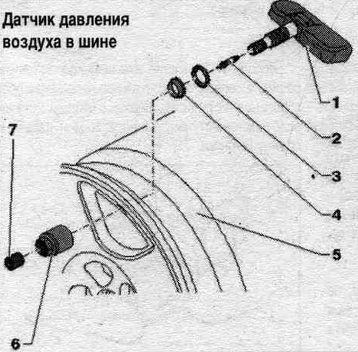
1. Front left wheel pressure sensor "6222", front right wheel "G223", rear left wheel "G224" or rear right wheel "G225"; every time you change your tires, replace the valve core: when using a used tire pressure sensor, the union nut, valve core, sealing ring, sealing washer, and valve cap must be replaced; after installation, conduct a visual inspection to ensure the sensor is firmly seated in the rim; damaged sensors should be replaced; do not clean sensors with jets of steam or a strong jet of compressed air.
2. Valve core: damaged valves should be replaced; when changing a tire, also replace the valve core.
3. Sealing washer: When installing a new sealing washer, avoid squeezing the valve body when holding it; if the connection is broken, replace the tire pressure sensor.
4. Sealing ring; when installing a new seal. rings to avoid squeezing the valve body when holding, if the connection is broken, replace the tire pressure sensor.
5. Rim.
6. Union nut: 8 Nm.
7. Cap: Use only original caps from the repair kit; do not use comfort caps.


Changing tires


Every time you change your tires, the nickel-plated valve core should be replaced. The tire pressure sensor can be reused. For safety reasons, after using tire sealant, you should replace the tire pressure sensor and clean the rim. Reduce tire pressure by removing the nickel-plated valve stem. Remove the tire. When replacing the tire, also replace the valve core. Do not clean sensors with steam jets or strong jets of compressed air. When using a used tire pressure sensor, visually inspect the connection between the sensor and the metal valve for defects. Replace damaged sensors. When installing a new sealing washer and a new seal. rings to avoid squeezing the valve body when holding. If the connection is broken, replace the tire pressure sensor. Install the tire. Screw in a new, nickel-plated valve core. Inflate the tire. Balance the wheel.

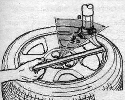
Removing the tire: Roll the tire or press it down. When using tire pushers, first push the tire on the side opposite the valve. Do not use pry bars in the shaded area "a". Position the pry head near the valve so that the mounting bar can be positioned at 30° "b" near the valve. Only then press the tire in the valve area.

Removing the tire: Roll the tire or press it down. When using tire pushers, first push the tire on…


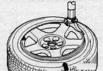
Tire installation: Do not use push-up tools in the valve area. Position the tire pressure sensor approximately 180° relative to the pressing head. Press the tire into the rim at a point approximately 90° from the "arrow" pressing head. Mount the tire.


Tire installation: Do not use push-up tools in the valve area. Position the tire pressure sensor…


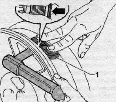
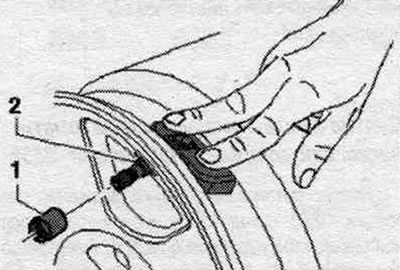
Removal and installation the tire pressure sensor


Unscrew the union nut "1". Remove the pressure sensor "2" from the rim base.

Unscrew the union nut «1». Remove the pressure sensor «2» from the rim base.


Installation


Be sure to replace damaged sensors. When using used tire pressure sensors, check the connection between the tire pressure sensor and the valve for damage. For safety reasons, after using tire sealant, replace the tire pressure sensor and clean the rim. Do not clean tire pressure sensors with steam or high-pressure air jets. When installing a new sealing cuff and sealing washer, avoid squeezing the valve body when holding (risk of damage to the antenna connection). Insert sensor "2" with a new seal. ring and sealing washer from the inside through the disk and press the seal. ring in the center of the valve hole. Perform a visual inspection to ensure that the valve stem is centered in the valve bore. Screw the union nut "1" onto the tire pressure sensor "2". Press the sensor into the rim and hold it there. When tightening the union nut, avoid applying strong pressure to the union nut and tool. Press the tire pressure sensor "1" to the bottom of the rim and tighten the union nut. After installation, the tire pressure sensor should fit firmly against the bottom of the rim. The "arrow" sealing washer is slightly deformed when tightened.


Be sure to replace damaged sensors. When using used tire pressure sensors, check the connection…
The article was checked by auto expert Timur Bazhenov
This article is available at russian, bulgarian, belarusian, ukrainian, serbian, croatian, romanian, polish, slovak, hungarian

Share information:
Previous articles
Audi A4 B8: Front suspension
Next articles

Tire Pressure Monitoring System (TPMS)
Constant velocity joint outer — repair and inspection
AAR 2600i or 3300i forged tripod joint — disassembly and assembly
Drive shaft


Similar articles on other Audi car models:
Fuel level sensor — removal and installation Audi 80 B3 (1986-1991, petrol)
Coolant Temperature Sensor — Removal and Installation Audi 100 C3 (1982-1990, diesel)
Removal and installation the fuel pump / fuel level sensor Audi A3 Type 8L (1996-2003)
Speedometer sensor — removal and installation Audi A6 C5 Allroad (1999-2005)
Removal and installation the engine Audi A8 D2 (1994-2002)
Removal the tire pressure sensor Audi Q5 Type 8R (2008-2017)
Removal and installation the oil pressure sensor Audi A2 (1999-2005)
Link to this page in different formats


Visitor comments

No comments yet


How much will 39 + 12 =


A4(B8, 2007-2015) 
  • General information
  • Operating instructions
  • Power unit
  • Petrol engines 1.8 l
  • Petrol engines 1.8/2.0 l
  • Petrol engines 3.0 l
  • Petrol engines 3.2 l
  • Fuel system (petrol)
  • Diesel engines 2.0 l (CA*)
  • Diesel engines 2.0 l (CJCB)
  • Diesel engines 2.7/3.0 l
  • Diesel engines 3.0 l
  • Fuel system (diesel)
  • Transmission
  • Manual gearbox 0B1
  • Manual gearbox 0B2
  • Manual gearbox 0B3
  • Manual gearbox 0B4
  • Automatic transmission 0B5
  • Automatic transmission 0B6
  • Automatic transmission 0AW
  • All-wheel drive system
  • Chassis
  • Front suspension
  • Rear suspension
  • Brake system
  • Steering system
  • Body
  • Exterior
  • Interior
  • Seats
  • Doors, locks and windows
  • Security system
  • Heating and air conditioning
  • Electrical equipment
  • Audio system
  • Power devices
  • Equipment and devices
  • Lighting and lamps
  • Electrical circuits
 
A4(B7, 2004-2008) 
  • General information
  • Introduction to manual
  • Troubleshooting
  • Operating instructions
  • Maintenance
  • Power unit
  • Petrol engines 2.0 (ALT)
  • Petrol engines 2.0 (TFSI)
  • Petrol engines 1.8 (MPI)
  • Diesel engines
  • Cooling system
  • Air conditioner
  • Fuel and exhaust system
  • Ignition system
  • Starting and charging
  • Transmission
  • Clutch
  • Manual gearbox
  • Automatic gearbox
  • Drive shafts
  • Chassis
  • Brake system
  • Front suspension
  • Rear suspension
  • Steering
  • Body
  • Exterior
  • Interior
  • Electrical equipment
  • Equipment and devices
  • Lighting and signaling
  • Windscreen wipers and washers
  • Electrical diagrams
  • Electrical diagrams (since 2007)
 
A4(B6, 2000-2006) 
  • General information
  • Vehicle Description
  • User manual
  • Maintenance
  • Power unit
  • Gasoline engine
  • Diesel engine
  • Lubrication system
  • Cooling system
  • Supply system
  • Injection system
  • Exhaust system
  • Ignition and control
  • Transmission
  • Gear box
  • Clutch and drive shafts
  • Chassis
  • Brake system
  • Car suspension
  • Steering
  • Body
  • Heating and ventilation
  • Exterior (external elements)
  • Interior (internal elements)
  • Electrical equipment
  • Power devices
  • Lighting and appliances
  • Electrical circuits
 
A4(B6, 2000-2006, petrol) 
  • General information
  • Introduction to the guide
  • Car care
  • Power unit
  • Engine repair
  • Lubrication system
  • Cooling system
  • Injection and control system
  • Ignition system
  • Power and exhaust system
  • Transmission
  • Clutch and drive shafts
  • Car gearbox
  • Chassis
  • Suspension and wheels
  • Steering
  • Brake system
  • Body
  • Interior
  • Exterior
  • Electrical equipment
  • Equipment and devices
  • Lighting and signaling
  • Power devices
  • Electrical circuits
 
A4(B5, 1994-2001) 
  • General information
  • Introduction to the guide
  • Car care
  • Maintenance (gasoline)
  • Maintenance (diesel)
  • Power unit
  • Gasoline engines
  • Diesel engines
  • Engine overhaul
  • Cooling system
  • Fuel injection (gasoline)
  • Fuel system (diesel)
  • Exhaust system
  • Ignition system
  • Transmission
  • Clutch
  • Mechanical gearbox
  • Automatic gearbox
  • Drive shafts
  • Chassis
  • Brake system
  • Car suspension
  • Steering
  • Body
  • Exterior
  • Interior
  • Doors, locks and windows
  • Heating and ventilation
  • Electrical equipment
  • Power devices
  • Equipment and devices
  • Electrical circuits
 
A4(B5, 1994-2001, petrol) 
  • General information
  • Vehicle description
  • Maintenance
  • Power unit
  • Engine repair
  • Turbocharging
  • Exhaust system
  • Cooling system
  • Ignition system
  • Fuel system
  • Motronic injection system
  • MPI and MPFI injection system
  • Transmission
  • Clutch
  • Gearbox and shafts
  • Chassis
  • Steering
  • Car suspension
  • Brake system
  • Wheels and tires
  • Body
  • Heating and ventilation
  • Body parts
  • Electrical equipment
  • Fuses and relays
  • Power devices
  • Lighting and lamps
  • Tools and devices
  • Electrical circuits
 
AudiManual.ru © 2017-2026 · Mobile version · Feedback · Sitemap: EN BG BY UA RS HR RO PL SK HU · Site search · News and articles
80 B2 · 80 B3 petrol · 80 B3 · 80 B4 · 100 C3 diesel · 100 C3 petrol · 100 C3 · 100 C4 petrol · 100 C4 · A3 Type 8L · A4 B5 petrol · A4 B5 · A4 B6 petrol · A4 B6 · A4 B7 · A4 B8 · A6 C4 · A6 C5 · A6 C5 Allroad · A8 D2 · Q5 Type 8R · Q7 Typ 4L · Audi A2 ·
This site uses cookies 🍪. Click the button to accept this fact.