
Table of contents: Repair of the outer constant… ↓ Checking the outer CV joint ↓
Repair of the outer constant velocity joint
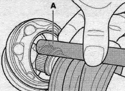
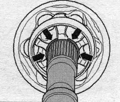
Removing the outer CV joint: Clamp the drive shaft in a vice with protective jaw pads. Open both clamps and remove the boot from the outer joint. Using a hammer and a copper or brass punch "A," strike the inner CV joint race. Remove the joint and the joint boot.
Install the outer CV joint: There should be no grease on the joint boot and drive shaft. Retaining ring (lock ring) "1" must be replaced. Slide the small terminal clamp with the hinge cover on and set the hinge cover to the position depending on the version.
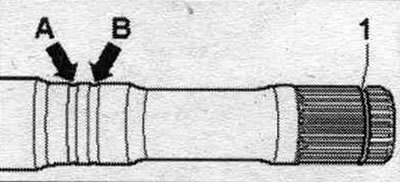
Design with marking groove: Position the joint boot in the outer groove "arrow B". The inner groove "arrow A" must not be covered by the "control groove" (to determine the correct installation of the hinge boot).
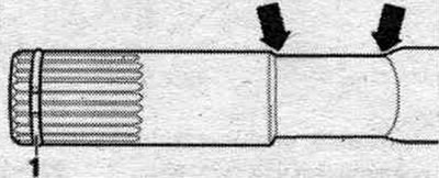
Deep groove version: Position the joint boot between the "arrows." Fill the inside of the joint with the specified amount of grease.
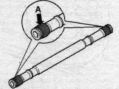
Before installing the hinge, the teeth "A" must be coated with a thin layer of grease used for the hinge. Insert the retaining ring into the shaft groove.
Slide the constant velocity joint up to the retaining ring. Align the retaining ring with the hole facing up and centered "see arrows".
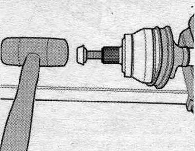
Screw the old axle joint bolt into the joint element as shown in the picture. Use a plastic hammer to tap the joint onto the drive shaft until the locking ring snaps into place.
Fill the hinge on the boot side with the specified amount of grease. Slide the boot onto the hinge element. Release air from the protective boot of the hinge. Ensure that the boot is correctly positioned on the joint. The boot must fit into the groove and around the perimeter of the hinge housing. Tighten the clamps on the outer hinge.
Checking the outer CV joint
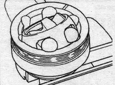
The joint must be disassembled to replace the lubricant if it is heavily contaminated, and to inspect the surfaces in contact with the balls for wear and pitting. Before disassembling, mark the position of the inner race in relation to the separator and housing with an engraving machine or a whetstone. Turn the clip and separator. Remove the balls one by one.
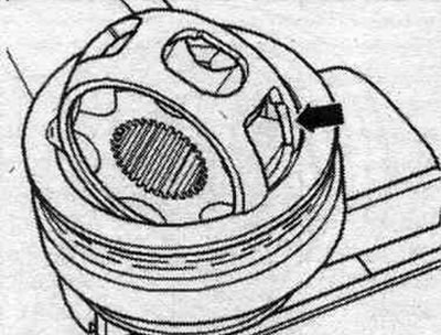
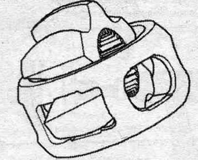
Install the separator with the cage so that the 2 rectangular cutouts of the separator "arrow" coincide with the protrusions on the outer cage of the CV joint (in the hole of the hinge housing). Remove the clip and separator.
Turn the side of the hinge sleeve with the shortened protrusion into the rectangular window of the separator. Remove the clip from the separator.
Check: The balls of each joint belong to the same tolerance group. Check the splines, separator, race and balls for indentations (pitting) and signs of heavy wear. Excessive angular clearance in the joint is noticeable when the load changes; in such cases, the joint must be replaced. Matting of the ball surface and the presence of tracks from them are not reasons for replacing the joint.
Assembly: Insert the collar and separator into the hinge housing. The separator must be correctly oriented to the sides. Place the balls crosswise. When assembling, install the collar in relation to the separator in accordance with the applied marks. Fill the hinge housing with a certain amount of grease.
The original publication in its entirety is posted on the website AudiManual