
Table of contents: Drive shaft ↓ Removal and installation the drive… ↓
Drive shaft
AAR 2600 i hammered tripod joint with 85/88 mm outer CV joint
AAR 3300 i hammered tripod joint with outer CV joint diameter 94/100 mm
AAR 3300 i hammered tripod joint with outer CV joint diameter 99/106 mm
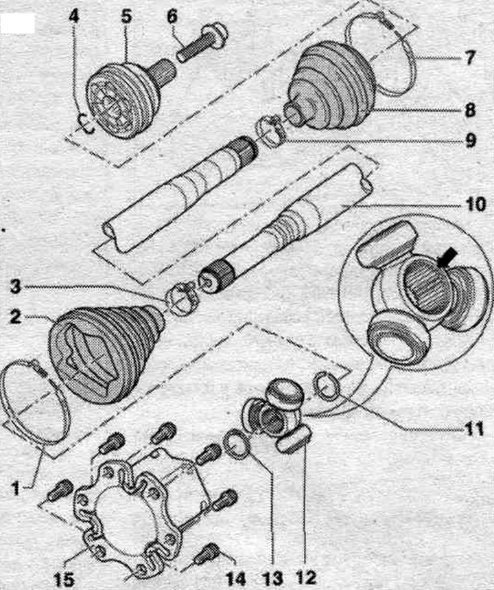
1. Clamp: replace when removed.
2. Protective cover with adapter for tripod joint: the boot should fit in the groove and along the perimeter of the joint housing; before tightening the clamping collar, lift the joint boot briefly to equalize the pressure.
3. Clamp: replace when removed.
4. Retaining ring: replace when removing, install in the annular groove of the shaft before installation (when the hinge is assembled it is not visible); before installing the constant velocity joint, align the retaining ring with the center of the hole by moving it upwards.
5. Outer CV joint: can only be replaced as an assembly; when mounting a hinge on a profiled shaft, the teeth of the profiled shaft must be coated with a thin layer of grease used for the hinge.
6. Bolt: 200 Nm + 180°; replace when removed;before tightening the threaded connection, clean the CV joint threads with a tap; follow the procedure for loosening and tightening the threaded connection of the drive shaft on the wheel hub.
7. Clamp: replace when removed.
8. Outer CV joint boot: check for cracks and wear; before tightening the clamping collar, lift the joint boot briefly to equalize the pressure.
9. Clamp: replace when removed.
10. Drive shaft.
11. Retaining ring.
12. Tripod joint sprocket: the "arrow" chamfer is directed towards the splines of the drive shaft; when mounting a tripod joint sprocket on a profiled shaft, the teeth of the profiled shaft must be coated with a thin layer of grease used for the joint.
13. Retaining ring: replace when removing: install in the shaft groove.
14. Bolt.
15. Hinge element.
If the drive shaft threaded connection on the wheel side is loose, do not allow load to be placed on the hub bearings. If the wheel bearings are subjected to the vehicle's own weight, they may be damaged. This will reduce the service life of the wheel bearings. Therefore, it is necessary to take into account the following. It is prohibited to move the vehicle without the drive shafts installed, as this will damage the wheel hub bearing. If, however, the vehicle needs to be moved, the following must be observed. Install the outer CV joint in place of the drive shaft. Tighten the outer CV joint to 200 Nm. During installation, do not allow the drive shaft to hang freely, as bending it will damage the inner joint.
Removal and installation the drive shaft
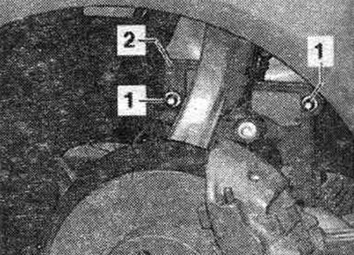
Unscrew the bolts securing the drive shaft to the wheel hub. Remove the wheel. Unscrew nut "1" and remove casing "2".
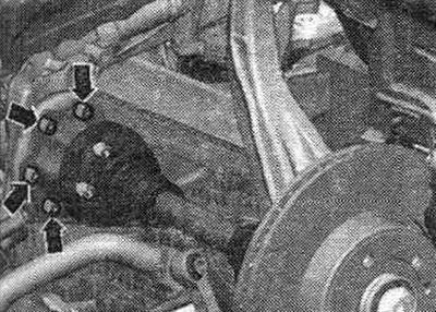
Unscrew the "arrow" bolts from the shaft with flange/gearbox. Remove the drive shaft.
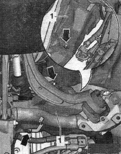
Only on vehicles with a subframe shield: If there is not enough free space to remove the drive shaft, the following steps must be taken. Unscrew the "arrow" bolts and place the subframe shield "1" to the side. Remove the brake bracket. hose and wire system. ABS from the wheel bearing housing.
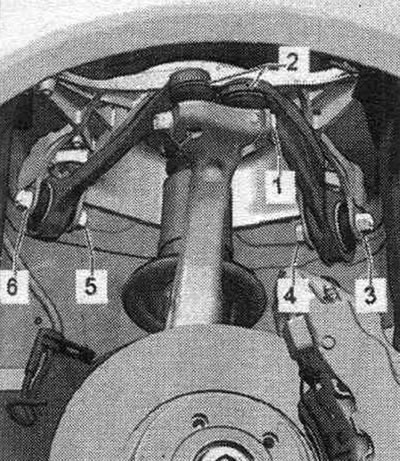
Loosen bolt connection "1" and remove both suspension arms "2" in an upward direction. Flaring the splines in the hub bearing housing using a chisel or similar tool is not permitted! Rotate the hub bearing housing to the side while pulling the drive shaft pin out of the wheel hub. Remove the drive shaft.
Installation
Installation in reverse order. Insert both upper control arm pivot pins "2" into the hub bearing housing and insert bolt "1". When tightening, press the upper control arm as far down as possible! Tighten bolt connection "1". Install the wheel. Tighten the wheel. Tighten the drive shaft to wheel hub mounting bolts.