



Table of contents: Support arm, ball joint, guide arm,… ↓ Removal and installation the control… ↓ Removal and installation the… ↓ Removal and installation the guide… ↓ Body level sensor ↓
Support arm, ball joint, guide arm, vehicle level sensor
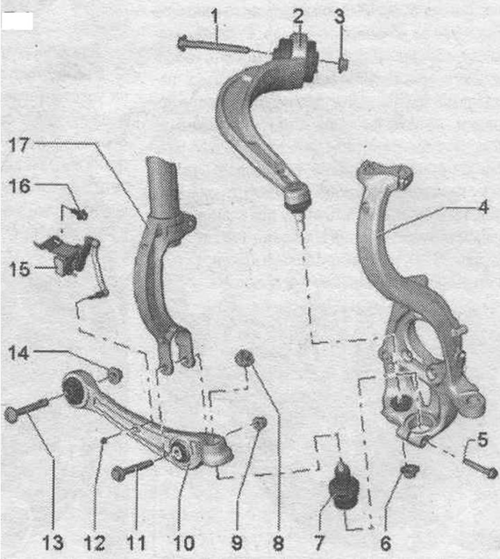
1. Bolt: Replace when removed.
2. Guide arm: It is not allowed to install 2 different types of racks at the same time.
3. Nut: 70 Nm + 180°; replace when removed; tighten only when the vehicle is in a no-load position.
4. Hub bearing housing.
5. Bolt: 40 Nm; replace when removed.
6. Nut: Replace when removed; take into account the features of nuts of different designs and the requirements for tightening torques; After loosening the bolt connection of the guide lever on the hub bearing housing, it is necessary to remove any remaining glue from the pin threads.
7. Suspension joint. Take into account the installation. position. Install the suspension arm into the wheel bearing housing so that it touches the supporting surface.
8. Nut: Replace when removed; various designs; take into account the features of nuts of different designs.
9. Nut: 90 Nm + 90°; replace when removed; tighten only when the vehicle is in a no-load position.
10. Carrying lever.
11. Bolt: Replace when removed.
12. Nut: 9 Nm.
13. Bolt: replace when removed.
14. Nut: 70 Nm +180°; replace when removed; tighten only when the vehicle is in a no-load position.
15. Ground clearance sensor, front left "G78" or front right "G289": install only a sensor of the same design: remove; install or replace only as a complete unit; the sensor lever must be facing backwards; after loosening, check the basic headlight setting; after removing and installing the door sensor. clearance or detachment of rods on vehicles with an electric system. the damping adjustment position must be readjusted; if the control position is re-adapted on a vehicle with lane departure warning system, the lane departure warning system control unit "J759" must be recalibrated.
16. Bolt: 20 Nm.
17. Shock absorber fork.
Designs of nuts for fastening the carrier and guide lever
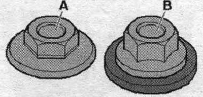
Hexagonal flange nut "A" M12, spanner size 21 mm. Tightening torque: 145 Nm.
Hexagonal combination nut "A" M12, spanner size 18 mm. Tightening torque: 110 Nm.
Hexagonal combination nut "A" M12, spanner size 21 mm. Tightening torque: 120 Nm.
Hexagonal combination nut "A" M14, spanner size 21 mm. Tightening torque: 140 Nm.
Removal and installation the control arm
Remove the wheel. Remove sound insulation. On a car with a road sensor. unscrew the nut "2" from the clearance. Disconnect the bolt connection "3".
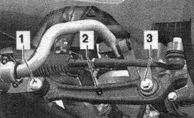
Unscrew nut "1" of the cross steering wheel tip pin. rod "2" until it is flush with the thread of the finger. When loosening, if necessary, hold it from turning. To protect the threads, leave the nut on the pin screwed on for a few turns. Press out the crossbar tip. remove the rods from the hub bearing housing using the T40010 A ball joint puller. Then unscrew the nut. Make sure that both arms of the puller lever are parallel to each other at the moment of maximum force application; correct the position if necessary.
Disconnect bolt connection "1". To remove bolt "1", depending on the side of the car, turn the steering wheel. mechanism all the way to the left or right. Remove the support arm from the mount and move it back. Loosen the ball joint pin nut until it is flush with the ball joint pin threads. When loosening, if necessary, hold it from turning. Press out the ball joint pin from the conical socket using the T40010 A ball joint puller. Make sure that both arms of the puller lever are parallel to each other at the moment of maximum force application; correct the position if necessary. Be careful not to damage the ball joint boot! To prevent damage to the upper control arm ball joints, use a VAG 1383 A engine and transmission lift, for example, to support the wheel bearing housing against the shock absorbers' reverse motion. Unscrew the nut from the pivot pin of the control arm. Remove the support arm.
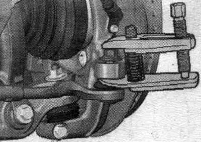
Installation
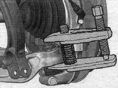
Installation in reverse order. Silent blocks have a limited torsional working range. Therefore, wheel suspension bolt connections should only be tightened when the vehicle is in the unloaded or standard suspension position. Raise the wheel support to the unloaded suspension position. When tightening threaded connection "1," the control arm must be pressed toward the inside of the vehicle. Remove any remaining adhesive from the ball joint pin threads. For vehicles with automatic headlight range control, perform basic headlight installation. After removing and installing the door sensor. clearance or detachment of rods on vehicles with an electric system. reg, the damping adjustment position should be readjusted. If the steering position is re-adapted on a vehicle with lane assist, the lane assist control unit "J759" must be recalibrated. Tighten the wheel.
Removal and installation the suspension joint
Remove the support arm. Unscrew bolt "1".
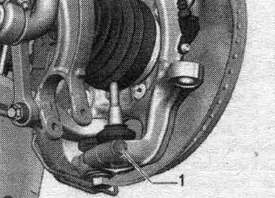
Insert the seal. washer or similar part "2" into the spline of the hub bearing housing. The thickness of the sealing washer or similar part must exactly match the width of the slot. Screw in bolt "1" until it touches the rear. sides of a sealing washer or similar part. Screw in bolt "1" further (half a turn), to widen the spline of the hub bearing housing. Remove the ball joint from the hub bearing housing.
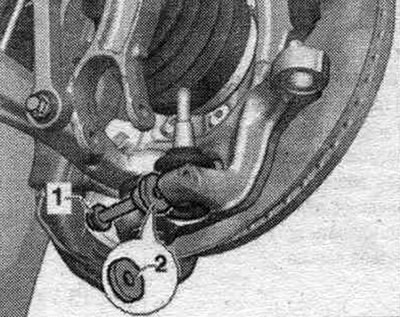
Installation
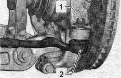
Installation in reverse order. Insert suspension joint "1" into hub bearing housing "2" up to the "arrow" bearing surface. If suspension joint "1" does not touch the "arrow" bearing surface, this may cause damage to the bolted connection area on hub bearing housing "2.".
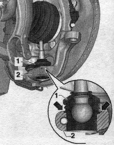
Install the support arm. Tighten the wheel.
Removal and installation the guide lever
In the 2010 model year, the standard silent block control arms were gradually replaced by hydraulic control arms. silent block. Installing control arms with different silent blocks on the same axle is not permitted. Remove the wheel. Remove sound insulation. If present, unscrew the "arrow" bolts and place the subframe shield "1" to the side. Loosen the guide arm pivot pin nut until it is flush with the pivot pin threads. If necessary, hold the steering wheel from turning.
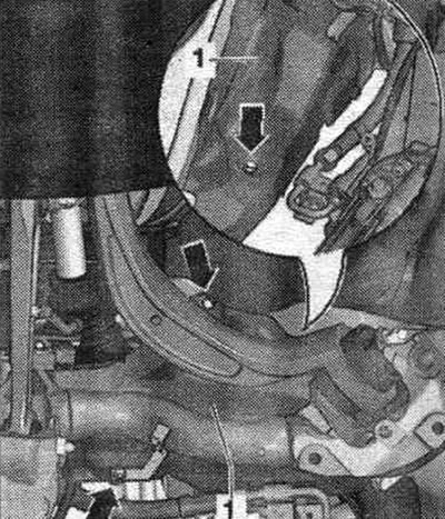
To protect the threads, leave the nut on the pin screwed on for a few turns. Press out the guide arm hinge pin from the conical socket using the T40010 A ball joint puller. Be careful not to damage the joint boot! Ensure that both arms of the puller lever are parallel to each other when maximum force is applied.
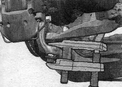
Disconnect bolt connection "1". Remove the guide lever.
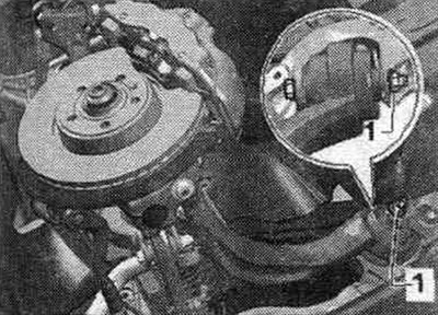
Installation
Installation in reverse order. Remove any remaining adhesive from the threads of the guide lever pin. Silent blocks have a limited torsional working range. Therefore, wheel suspension bolt connections should only be tightened when the vehicle is in the unloaded or standard suspension position. Raise the wheel support to the unloaded suspension position. When tightening bolt connection "1", the guide lever must be pressed towards the inner side of the car. Tighten the wheel.
Body level sensor
Car with electric system. adjustable damping and/or with gas discharge lamps are equipped with dynamic headlight range control as standard. The damping control system and the dynamic headlight range control require information about the compression and rebound stroke of the front springs to operate. suspension and rear. axles. For this purpose, the position of the left/right control arm relative to the body is transmitted via a connecting rod to the front left door sensor. clearance "G78" and front right door sensor. clearance "G289". They transmit electrical signals to the control unit of the system. electrical control, damping "J250" and/or left/right gas discharge lamp control unit -J343/344-. To the rear axle from the road sensor. rear clearance. left "G76" and door sensor. rear clearance. right "G77" these signals are transmitted to the control unit of the system. electrical control, damping "J250" and/or to the left/right gas discharge lamp control units -J343/344-. These signals are necessary to determine the vehicle level. The automatic headlight range control reacts automatically to changes in road. ground clearance. The vehicle's ground clearance may change in the following situations: working with a trailer, various vehicle load conditions; the vehicle is unloaded, the vehicle is partially or fully loaded. On vehicles with an electric system. adjustment, damping adaptation of the adjustment position and checking of the main headlight adjustments is essential in the following cases: the support arm was removed and installed; the subframe was replaced; installation work was carried out on the vehicle's level sensor; the vehicle's level sensor was replaced; the bolted connection of the connecting rod from the door sensor was loosened. clearance on the support arm. On vehicles with an electric system. reg, damping adjustment position has been re-adapted. If the control position is re-adapted on a vehicle with lane departure warning system, the lane departure warning system control unit "J759" must be recalibrated.
Removal
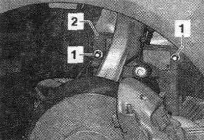
Unscrew nut "1" and remove casing "2".
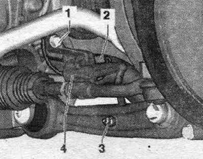
Disconnect connector "2". Unscrew nut "3". Unscrew bolt "1". Remove the door sensor. clearance of the car "4".
Installation
Installation in reverse order. Install only a sensor of the same design. The retainer on the sensor holder must be installed in the subframe. The sensor lever must be facing backwards. After loosening, check the basic setting of the headlights. After removing and installing the vehicle level sensor or loosening the rods on a vehicle with an electrical system. damping adjustment, the suspension should be re-adjusted to its standard position. If the control position is re-adapted on a vehicle with lane departure warning system, the lane departure warning system control unit "J759" must be recalibrated.
(Information obtained from this resource: audimanual.ru)