



Table of contents: Subframe, crosspiece, stabilizer,… ↓ Removal and installation the subframe ↓ Removal and installation the… ↓ Removal and installation the… ↓ Removal and installation the… ↓ Removal and installation the… ↓
Subframe, crosspiece, stabilizer, connecting rod, subframe shield
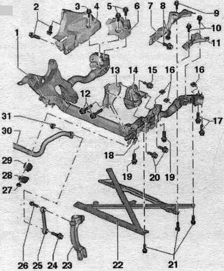
1. Subframe.
2. Bolt: 9 Nm.
3. Bolt: 20 Nm.
4/6/7/11. Subframe shield: installed depending on the engine model.
5. Bolt: 20 Nm.
8. Bolt: 9 Nm.
9/10. Bolt: 20 Nm.
12. Bolt.
13. Engine bracket mounting plate.
14. Engine mount.
15. Bolt.
16. Square nut: replace when removed.
17. Bolt: 115 Nm + 90°; replace when removed.
18. Mounting pin: Can be replaced if damaged.
19. Bolt: 115 Nm + 90°: replace when removed.
20. Bolt.
21. Bolt: 90 Nm + 90°; replace when removed.
22. Cross connection of subframe stretchers. Never lower the vehicle onto its wheels unless the subframe support, steering gear, or subframe cross-joint are properly installed.
23. Shock absorber fork.
24. Bolt: 40 Nm + 90°; replace when removed; tighten only when the vehicle is in a no-load position.
25. Connecting rod: take into account the different designs: made of aluminum and steel, compliance; simultaneous installation of 2 racks of different types is not allowed.
26. Bolt: 40 Nm + 90°; replace when removed; tighten only when the vehicle is in a no-load position.
27. Nut: 25 Nm; replace when removed, tighten only when the vehicle is without load.
28. Clamp.
29. Rubber cushion: the silent block hole must face the subframe during installation; the stabilizer and rubber cushion must be degreased during installation.
30. Stabilizer.
31. Nut: Replace when removed.
Removal and installation the subframe
Remove the wheels. Remove the wheel arch liners on the left and right. Remove sound insulation. Remove the cross connection of the stretchers. If present, remove the subframe shield on the left and right. Remove the stabilizer. Take off (if available) door sensor. clearance.
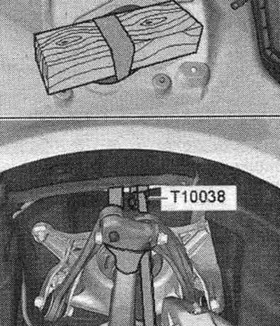
Tie the wheel bearing housing on the left and right, as shown in the figure, using the tension belt "T10038".
Remove the left and right suspension arms. Remove the steering gear. Secure the engine assembly using a crossmember. On the left and right, unscrew the bolts "1" and nuts "3" and remove the longitudinal braces "2".
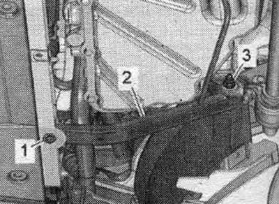
Disconnect bolt connection "1". Tilt the guide lever and secure it to the body with wire or similar material.
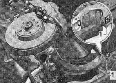
On a vehicle with an electric hydraulic system, engine mount, disconnect the plug connector "arrow" of the left electric hydraulic system, engine mount "N144" and the right electric hydraulic system. hydraulic, engine mounts "N145". Depending on the installed engine, unscrew nut "2" of the wire bracket on the right side of the vehicle.
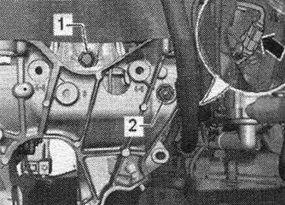
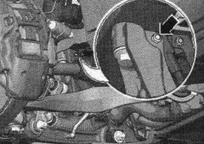
Unscrew the bolt of the "arrow" power steering line bracket.
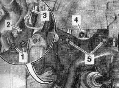
Remove bolts "1 and 5" of the left and right engine mounts. Move the mounting plate "2" of the left and right engine mounts to the side. Before lowering the subframe, check that all wire connections are disconnected or removed. Mark the installation position of the subframe from "A" to "D", for example, with a felt-tip pen. Unscrew bolts from "1" to "8" and remove the subframe.
Installation in reverse order.
Procedure for tightening the subframe threaded fasteners
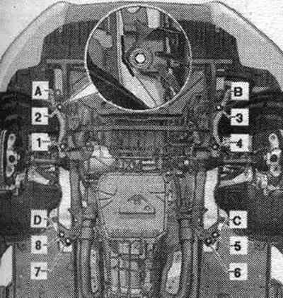
Install the subframe and align it with the previously made marks "A" and "B", tighten bolts "2" and "3" only to the prescribed torque. Press the subframe to the marks "C" or "D", tighten bolts "5" and "8" to the specified torque. Screw in the bolts "1", "4", "6" and "7" and tighten them to the specified torque. Tighten bolts from "1" to "8" to the prescribed angle. Silent blocks have a limited torsional working range. Therefore, wheel suspension bolt connections should only be tightened when the vehicle is in the unloaded or standard suspension position. Raise the wheel support to the unloaded suspension position. For vehicles with automatic headlight range control, perform basic headlight installation. After removing and installing the door sensor. clearance or detachment of rods on vehicles with an electric system. the damping regulator must be re-adapted to the adjustment position. If the steering position is re-adapted on a vehicle with lane assist, the lane assist control unit "J759" must be recalibrated. Tighten the wheel. The need to adjust the wheel alignment angles.
Removal and installation the cross-joint of the subframe struts
Remove sound insulation. Remove bolt "1" from the power steering line bracket. Remove the "arrow" bolts and remove the cross-connection of the struts. If present, remove the subframe shield on the left and right.
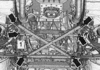
Remove the 4-sided arrow nuts from the cast sockets. Never lower the vehicle onto its wheels unless the subframe support, steering gear, or subframe cross-joint are properly installed.
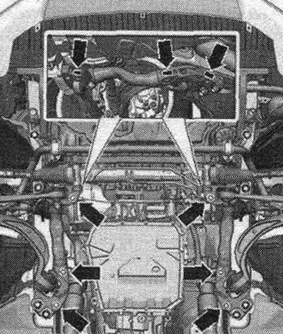
If the car needs to be rolled, it is necessary to install the cross-connection of the tie rods with the old bolts and square nuts in place and tighten them to the prescribed torque without turning further.
Installation
Installation in reverse order. On vehicles with subframe shields, square nuts should be inserted into the casting sockets before installing the shields.
Removal and installation the stabilizer
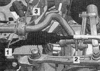
Remove sound insulation. Disconnect bolt connection "2" on the left and right. Unscrew nuts "1" on the left and right and remove clamps "3". Remove the stabilizer.
Installation
Installation in reverse order. Silent blocks have a limited torsional working range. Therefore, wheel suspension bolt connections should only be tightened when the vehicle is in the unloaded or standard suspension position. Raise the wheel support to the unloaded suspension position. When replacing the stabilizer, pay attention to the design of the chassis. The stabilizer and support must be degreased. Install the rubber mounts with the hole facing the subframe mating surface. Tighten nuts "1" but do not tighten. Tighten bolt connection "2" on the left and right, but do not tighten. Tighten bolt connections "1" and "2".
Removal and installation the connecting rod
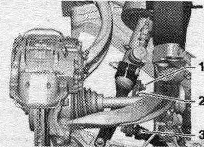
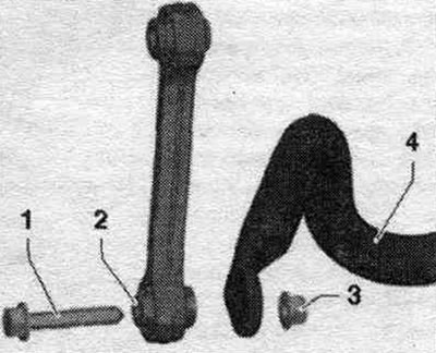
In the 2010 model year, the aluminum tie rods were gradually replaced by plastic tie rods. Installation of different connecting rods on one axle is not permitted. Disconnect bolted connections "1" and "3". Remove connecting rod "2".
Installation
Installation in reverse order. Take into account the installation. position of the connecting rod. Silent blocks have a limited torsional working range. Therefore, wheel suspension bolt connections should only be tightened when the vehicle is in the unloaded or standard suspension position. Raise the wheel support to the unloaded suspension position. Bolt "1" for fastening the connecting rod to the stabilizer "4" must be installed on the "small" surface "2" of the flange of the connecting rod and tightened with nut "3".
Tighten the bolt connection "1" and "3" but do not tighten. Raise the wheel support to the unloaded suspension position. Tighten bolt connections "1" and "3".
Removal and installation the subframe shield
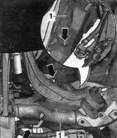
Remove the cross connection of the stretchers. Unscrew the "arrow" bolts. Remove the subframe shield "1" inward.
Installation
Installation in reverse order. Before installing the subframe shield, insert the square nuts into the cast sockets.