
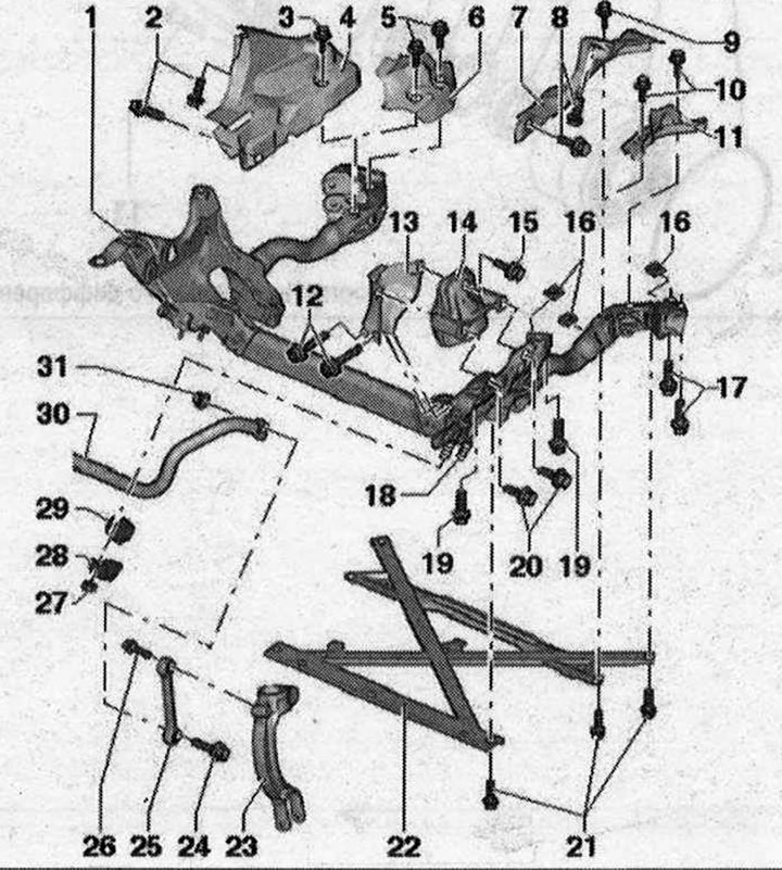
I 1. Subframe; 2/8. Bolt. 9 Nm; 3/5/9/10. Bolt. 20 Nm; 4/6/7/11. The subframe shield is installed depending on the engine model; 12/15/20. Bolt; 13. Engine bracket mounting plate; 14. Engine mount; 16. Square nut. Replace each time when removed; 17/19. Bolt. 115 Nm + turn 90°. Replace each time when removed; 18. Locating pin. Can be replaced if damaged; 21. Bolt. 90 Nm + turn 90°. Replace each time when removed; 22. Cross connection of stretchers of the subframe. Risk of damage to chassis parts. Never lower the vehicle onto its wheels unless the subframe support, steering gear or subframe cross joint are properly installed. Supporting the vehicle on a subframe or cross stretchers of the subframe (for example, when using a rolling jack or the like.) not allowed!; 23. Shock absorber fork; 24/26. Bolt. 40 Nm + turn 90°. Replace each time removed. Tighten only in the vehicle position without load ' 25. Connecting rod. Consider different versions: aluminum and steel. Simultaneous installation of 2 racks of different types is unacceptable; 27. Nut. 25 Nm. Replace each time removed. Tighten only in the vehicle position without load; 28. Clamp; 29. Rubber cushion. When installing, the hole in the say-tape block must face the subframe. The stabilizer and rubber cushion must be degreased during installation; 30. Stabilizer; 31. Nut. Replace every time removed
Removing the subframe
Remove the wheels. Remove sound insulation. Remove the wheel arch liners on the left and right. Remove the cross connection of the guy wires. If equipped, remove the subframe shield on the left and right. Remove the stabilizer.
Applies to vehicles with hydraulic steering gear: Remove the steering gear.
Applies to vehicles with electro-mechanical steering gear: Remove the steering gear.
All
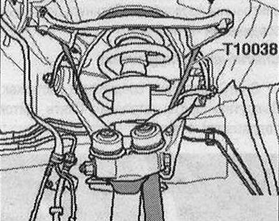
If there is a ride height sensor, remove it. Secure the wheel bearing housing on the left and right using a tensioning belt -T10038- to the support bracket as shown in the illustration. Remove the suspension control arms on the left and right. Using a traverse, secure the engine assembly.
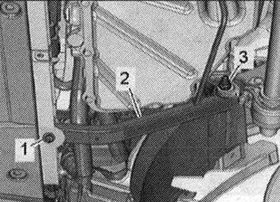
Unscrew the bolts -1- and nuts -3- on the left and right and remove the longitudinal braces -2-.
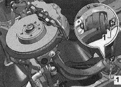
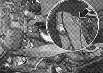
Disconnect bolt connection -1-. Move the guide arm and secure it to the body with wire or similar material.
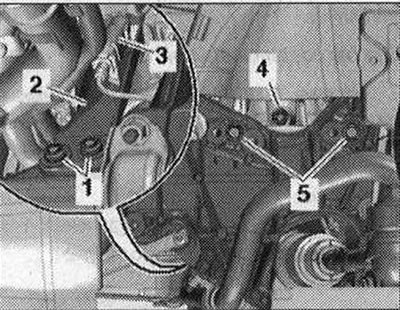
On vehicles with electro-hydraulic engine mount, disconnect the connector -arrow- of the left electro-hydraulic engine mount -N144- and the right electro-hydraulic engine mount -N145-. Depending on the installed engine, unscrew the nut -2- of the electric bracket. wires on the right side of the car.
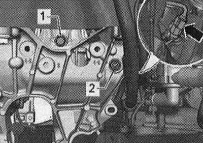
Applies to vehicles with hydraulic steering: Unscrew the bolt for the power steering line bracket -arrow-.
Remove bolts -1 and 5- of the left and right engine mount. Move the mounting plate -2- of the left and right engine mounts to the side.
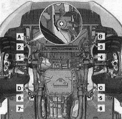
Before lowering the subframe, check that all electrical connections are complete. wires are disconnected or removed. Mark the installation position of the subframe from -A- to -D-, for example with a felt-tip pen. Unscrew bolts -1- to -8- and remove subframe.
Installation
Install in reverse order. In this case, tightening torques must be taken into account. Procedure for tightening the threaded fasteners of the subframe: Install the subframe and align it with the pre-made marks -A- and -B-, tighten bolts -2- and -3- only to the prescribed torque. Press the subframe towards marks -C- or -D-, tighten bolts -5- and -8- to the specified torque. Screw in bolts -4-, -6- and -7- and tighten them to the specified torque. Tighten bolts -1- to -8- to the specified angle. Say-tape blocks have a limited working range of twisting. Therefore, wheel suspension bolts should only be tightened when the vehicle is in the no-load or standard suspension position. Raise the wheel support with the suspension in static position on vehicles with coil springs. For vehicles with automatic transmission and headlight range control, perform the basic installation of the headlights. After removing and installing the vehicle level sensor or loosening the linkages on vehicles with electronic damping control, the standard suspension position must be readjusted. After readapting the adjustment position on vehicles with lane assist, the control unit for lane assist must be recalibrated. strip -J759-. Tighten the wheel. It is necessary to adjust the wheel alignment angles.
Visitor comments