



Table of contents: Wheel bearing housing, hub unit ↓ Removal and installation the wheel… ↓
Wheel bearing housing, hub unit
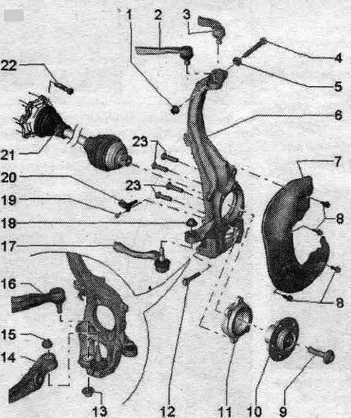
1. Nut: 40 Nm; replace when removed.
2. Upper front suspension arm.
3. Suspension arm at the top rear.
4. Bolt: Replace when removed.
5. Washer.
6. Hub bearing housing. When replacing the wheel bearing housing, ensure that the thread length on the steering column end is sufficient. traction (it is necessary to ensure a sufficient number of free threads) If there is not enough free threads, it is necessary to install a new crossbar tip. rods with longer threads.
7. Brake safety shield.
8. Bolt: 10 Nm.
9. Bolt: 200 Nm + 180°; replace each time after removal; before tightening the threaded connection, clean the CV joint threads with a tap.
10. Wheel hub.
11. Wheel bearing.
12. Bolt: 40 Nm; replace when removed.
13. Nut: Replace when removed; take into account the features of nuts of different designs and the requirements for tightening torques; after loosening the bolted connection of the guide lever on the hub bearing housing, it is necessary to remove any remaining glue from the pin threads.
14. Carrying lever.
15. Nut; replace when removed; take into account the features of nuts of different designs and the requirements for tightening torques; after loosening the bolted connection of the ball joint on the hub bearing housing, it is necessary to remove any remaining glue from the pin threads.
16. Guide lever.
17. Cross-rudder tip. traction.
18. Nut; read the features of nuts of various designs and tightening torque requirements; replace when removed.
19. Bolt: 9 Nm.
20. Speed sensor.
21. Drive shaft.
22. Bolt: 70 Nm; replace when removed.
23. Ball head screws: 80 Nm + 90°; replace when removed.
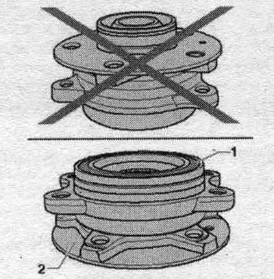
Hub bearing "1" must always point upwards. Always place the hub bearing assembly on wheel hub "2".
Designs of tie rod end fastening nuts. traction
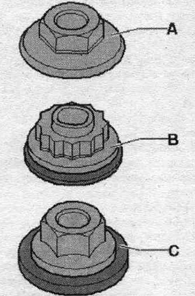
Hexagonal nut with flange "A". Tightening torque: 20 Nm + 90°.
Twelve-point combination nut "B". Tightening torque: 100 Nm.
Hexagon - combination nut "C". Tightening torque: 110 Nm.
Hub assembly with different thickness of steering pendulum arm
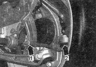
The hub assemblies differ in the thickness of the steering pendulum arm "2".
Removal and installation the wheel bearing housing
Two different wheel bearing housings were installed as standard; they differ in the thickness of the steering pendulum arm. When replacing the wheel bearing housing, ensure that the thread length on the steering column end is sufficient. traction (it is necessary to ensure a sufficient number of free threads) If there is not enough free threads, it is necessary to install a new crossbar tip. rods with longer threads. Unscrew the bolts securing the drive shaft to the wheel hub. Remove the support arm. Remove the brake holder from the wheel hub bearing housing. highways and wires. Remove the front speed sensor. Remove the brake caliper and secure it to the body so that its weight does not press on the brake. hose/brake line and did not damage it.
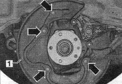
Remove the brake disc. Unscrew the bolts "arrows" and remove the brake protective shield "1". Unscrew the guide arm pivot pin nut until it is flush with the pivot pin threads. When loosening, if necessary, hold it from turning. To protect the threads, leave the nut on the pin screwed on for a few turns.
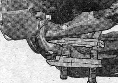
Press out the guide arm hinge pin from the conical socket using the T40010 A ball joint puller.
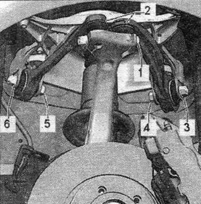
Disconnect bolt connection "1". Remove both upper suspension arm pivot pins "2" from the hub bearing housing. Flaring the splines in the hub bearing housing using a chisel or similar tool is not permitted! Remove the hub bearing housing from the drive shaft splines and remove the hub bearing housing. The drive shaft should not hang freely, as bending will damage the inner joint. Hang the drive shaft on a wire, attaching it to the body.
Installation
Installation in reverse order. Slide the wheel bearing housing onto the drive shaft splines. Insert both upper control arm pivot pins "2" into the hub bearing housing and insert bolt "1". Remove any remaining adhesive from the ball joint pin and guide arm threads. Attach the guide lever to the wheel bearing housing and tighten the threaded connection. When tightening, press the upper arm as far down as possible! Tighten bolt connection "1". Install the brake. disc and caliper. Tighten the drive shaft to wheel hub mounting bolts. For vehicles with automatic headlight range control, perform basic headlight installation. After removing and installing the door sensor. clearance or detachment of rods on vehicles with an electric system. reg, the damping adjustment position should be readjusted. If the steering position is re-adapted on a vehicle with lane assist, the lane assist control unit "J759" must be recalibrated. Tighten the wheel.