
Disassembly and assembly of a hammered tripoid joint AAR 2600 i or 3300 i
Disassembling the tripoid joint AAR 2600 i or 3300 i
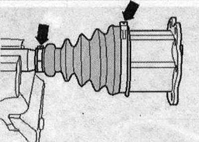
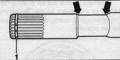
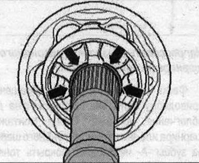
Clamp the drive shaft in a vice with protective jaw pads in a horizontal position. Use soft inserts for the vice. Make sure that the drive shaft is not damaged. Mark the position of the hinge part relative to the drive shaft. If they are not marked and are not installed in the same place during assembly, noise may occur later during operation. Mark the position of the boot relative to the hinge. A waterproof felt-tip pen is suitable for marking. Open clamps -arrows-. Move the hinge boot back.
Differences between AAR 2600 / and AAR 3300 i drive shafts
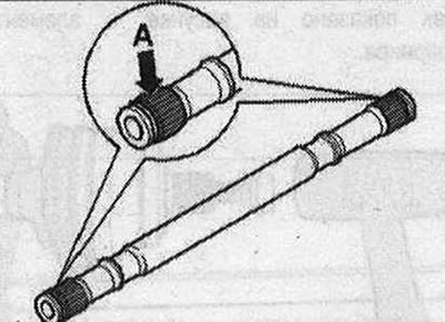
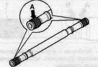
Determine dimension -A- as shown in fig.
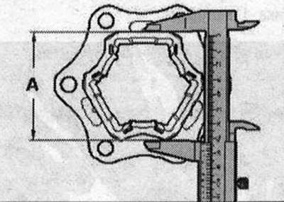
- Dimension -A- 74 mm = drive shaft AAR 2600 i
- Dimension -A- 77 mm = drive shaft AAR 3300 i
Carefully! Ensure that the appropriate special tools are used for each drive shaft.
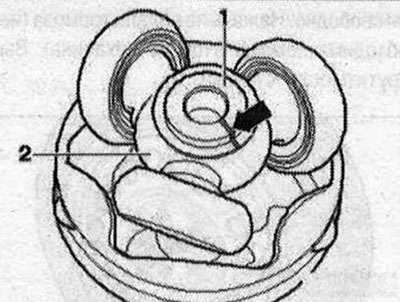
Insert assembly tool -T40018- for tripoid joint AAR 3300 i or assembly tool -T40084- for tripoid joint AAR 2600 i behind the hinge element. The guide pin -1- must be in contact with the outer side of the hinge part. Bring the assembly tool to touch the hinge part by turning the knurled screws -2-.
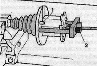
The hinge element must be fixed in the assembly tool -T40018- or T40084- without play. Tighten bolts -2- only by hand. Screw assembly tool -VW 771- into assembly tool -T40018- or -T40084-. In Fig. Assembly tool -T40018- for AAR 3300 i drive shaft is shown.
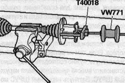
For the drive shaft of the AAR 2600 i, use assembly tool -T40084-. Remove the joint by pulling it horizontally using the inertial puller -VW 771-. Leave the hinge element in the assembly tool -T40018- or -T40084-. Mark the installation position of parts -1- and -2- with strokes. If they are not marked and are not installed in the same place during assembly, noise may occur later during operation. A waterproof felt-tip pen is suitable for marking.
- 1. Drive shaft
- 2. Tripoid joint sprocket.
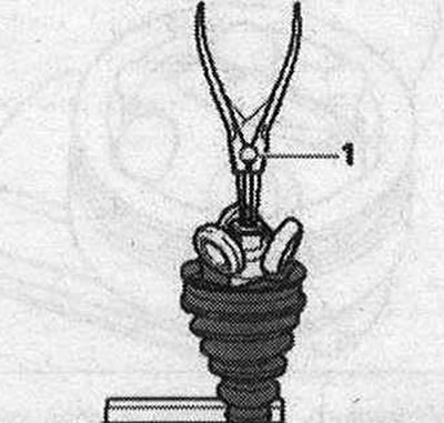
Remove the grease with a soft cloth. Remove the retaining ring using standard pliers -1-.
Press the tripod joint sprocket out of the drive shaft. Use the special tools shown in the illustration
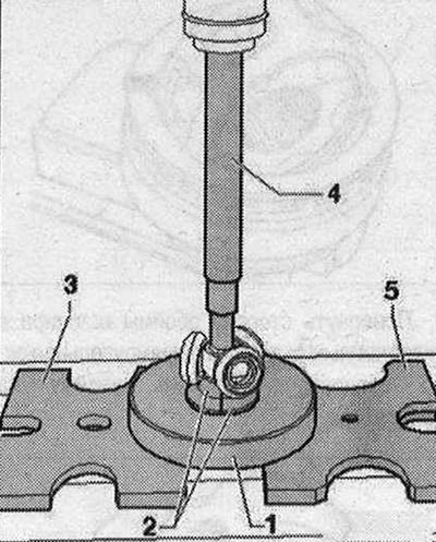
- 1. Mounting device -T10065/1-
- 2. The mounting device -T10065/5- must be in contact with the tripod joint sprocket
- 3. Pressure plate -VW 401 -
- 4. Mandrel -VW 408 A-
- 5. Pressure plate -VW 402-
The mounting device -T10065/5- must not touch the bearing rolling elements or move them to the sides. Remove the hinge boot. Remove grease from the shaft teeth. Check the wear of the rolling element and guide.
Clean the drive shaft and housing.
Tripod joint assembly AAR 2600 / or 3300 i
Push on the small terminal clamp with the hinge cover and install the hinge cover in a position depending on the design.
Version with marking groove: Position the joint boot in the outer groove -arrow B-. The inner groove -arrow A- must not close "control groove" (to determine the correct installation of the hinge boot).
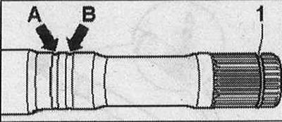
Version with deep seat groove: Position the joint boot between -arrows-.
Press the tripod joint sprocket onto the drive shaft
The chamfer on the tripod sprocket faces the drive shaft and is intended to facilitate installation. Before installing the joint or tripod joint sprocket, the teeth -A- must be coated with a thin layer of joint grease.
Install the tripod joint sprocket onto the shaft in accordance with the markings and push it all the way. Use the assembly tool -T10065/6-, making sure that it engages with the drive shaft at the bottom via the boss -arrow-. Use the special tools shown in the picture.
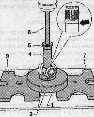
- 1. Mounting device -T10065/1-
- 2. The mounting device -T10065/6- must engage the boss -arrow- of the drive shaft from below
- 3. Pressure plate -VW 401-
- 4. Tubular insert -VW 416 B-
- 5. Thrust washer -VW 447 H-
- 6. Mandrel -VW411-
- 7. Pressure plate -VW 402-
The mounting device -T10065/6- must not touch the bearing rolling element or move it to the sides. Press the tripod joint sprocket onto the drive shaft. Install the retaining ring. The locking ring should click into place with an audible click and the sprocket should fit against the locking ring without play. Introduce 70 grams of drive shaft lubricant from the repair kit from the rear side of the tripoid joint. Lightly lubricate the rolling elements with grease. Make sure that the rolling elements do not warp! Using a plastic hammer, press the joint cage onto the tripod sprocket. In Fig. Assembly tool -T40018- for AAR 3300 i drive shaft is shown.
Inject the remaining lubricant into the joint boot. Push the boot onto the hinge element. Ensure that the boot is properly seated on the hinge and, if necessary, align the bellows. The boot should fit in the groove and along the perimeter of the hinge body. When installing the boot on the hinge, it is necessary to remove air from it. This can be done using a screwdriver. Install the clamp. To make it easier to install screws with an internal gear in the head when installing the drive shaft, it is necessary that the eye -2- of the clamp be between the mounting flanges -1- of the hinge part.
Press the clamp clamps onto the tripoid joint.
Visitor comments