
Table of contents: Loosening and tightening the… ↓ Removal the drive shaft ↓ Installation ↓ Volumes and type of lubricant ↓
If the drive shaft threaded connection on the wheel side is loose, do not allow the hub bearings to be loaded. If the hub bearings are subjected to the dead weight of the vehicle, they may be damaged. This will reduce the service life of the hub bearings. Therefore, the following must be observed: the procedure for loosening the drive shaft and wheel hub threaded connection. Do not move the vehicle without the drive shafts installed, as this will damage the wheel hub bearing. If the vehicle must nevertheless be moved, the following must be observed: install the outer CV joint instead of the drive shaft. Tighten the outer CV joint to a torque of 200 Nm. During installation work, the drive shaft must not hang freely, as bending will damage the inner joint.
Loosening and tightening the threaded connection of the drive shaft and wheel hub
Loosen the threaded connection of the drive shaft and the wheel hub. If the car is standing on its wheels, the bolt can be unscrewed by a maximum of 90°, otherwise the wheel hub bearing may be damaged. Raise the car so that the wheels hang freely. Press the brake pedal (assistance from a second mechanic is needed). Unscrew the "arrow" bolt.
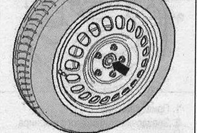
Tightening the drive shaft/wheel hub threaded connection. Replace the "arrow" bolt. Before tightening the threaded connection, clean the CV joint thread with a tap. When tightening the drive shaft, the wheels should not touch the floor; otherwise, damage to the hub bearing may occur. Press the brake pedal (assistance from a second mechanic is needed). Tighten the bolt to 200 Nm. Install the car on the wheels. Tighten the bolt by 180°.
Removal the drive shaft
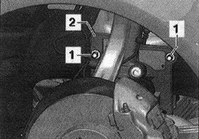
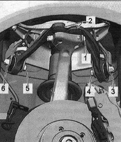
Unscrew the bolts securing the drive shaft to the wheel hub. Remove the wheel. Unscrew the nut "1" and remove the casing "2".
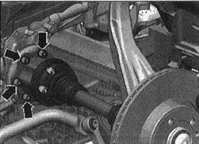
Unscrew the "arrow" bolts from the shaft with flange/gearbox. Remove the drive shaft.
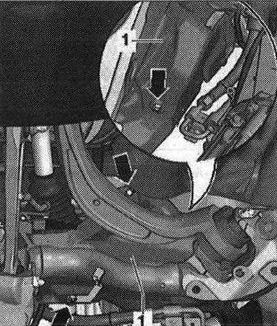
Only for vehicles with subframe shield: If there is not enough space to remove the drive shaft, the following steps must be taken: unscrew the bolts "arrows" and place the subframe shield "1" to the side.
Remove the bracket for the brake hose and ABS wire from the wheel bearing housing. Loosen the bolt connection "1" and remove both suspension arms "2" in an upward direction.
Flaring of the splines in the hub bearing housing using a chisel, etc. is not allowed! Turn the hub bearing housing to the side, while pulling the drive shaft pin out of the wheel hub. Remove the drive shaft.
Installation
Installation in reverse order. In this case, the following must be taken into account: insert both pins of the upper arms "2" into the hub bearing housing and insert bolt "1". When tightening, press the upper arm as far down as possible! Tighten bolt connection "1". Install the wheel. Tighten the wheel. Tighten the drive shaft mounting bolts to the wheel hub.
AAR 2600 i hammered tripod joint with 88 mm outer CV joint. AAR 3300 i hammered tripod joint with 100 mm outer CV joint
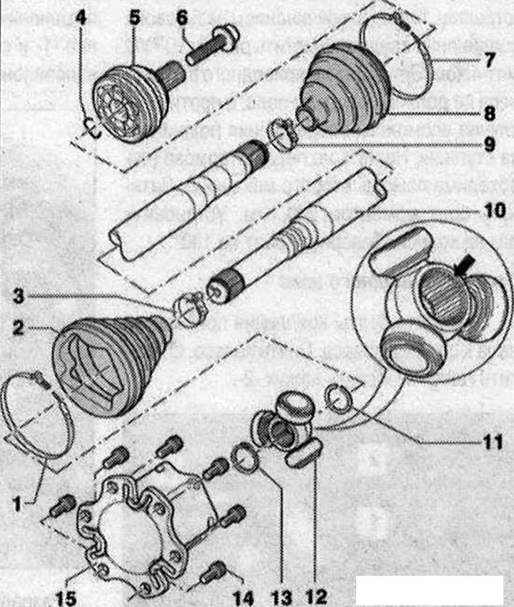
Drive shaft 1. Clamp. Replace each time it is removed; 2. Protective cover with adapter for Nira tripod ball. The boot should fit in the groove and along the perimeter of the joint housing. Before pressing the clamping clamp, lift the joint boot for a short time to equalize the pressure; 3. Clamp. Replace each time it is removed; 4. Retaining ring. Replace each time it is removed. Install into the shaft ring groove before installation (when the hinge is assembled it is not visible). Before installing the constant velocity joint, align the retaining ring with the center of the hole by moving it upwards; 5. Outer CV joint. Replaced only as an assembly. When installing the joint on a profiled shaft, the teeth of the profiled shaft must be coated with a thin layer of grease used for the joint; 6. Bolt. 200 Nm + tighten by 180°. Replace each time when removing. Before tightening the threaded connection, clean the CV joint thread with a tap. Follow the procedure for loosening and tightening the threaded connection of the drive shaft on the wheel hub; 7. Clamp. Replace each time it is removed; 8. Outer CV joint boot. Check for cracks and abrasions. Before tightening the clamp, lift the joint boot briefly to equalize the pressure.; 9. Clamp. Replace each time it is removed; 10. Drive shaft; 11. Retaining ring; 12. Tripod joint sprocket. The "arrow" chamfer is directed towards the splines of the drive shaft. When mounting a tripod joint sprocket on a profiled shaft, the teeth of the profiled shaft must be coated with a thin layer of grease used for the joint; 13. Retaining ring. Replace each time it is removed. Install it in the groove of the shaft; 14. Bolt; 15. Hinge element
Volumes and type of lubricant
When replacing the boot, re-lubricate the joint. Use different types of grease for the outer and inner joints.
| External hinge | Lubrication total volume | From this to the hinge | From this to Corrugated Case |
| 0 mm | [G] | [G] | [G] |
| 88 | 90 | 40 | 50 |
| 100 | 130 | 70 | 60 |