
Removal
1. Mark the direction of rotation of the wheel on the tire. Loosen the wheel mounting bolts. Raise and place the car on stands and remove the wheels.
Warning: Be sure to follow the instructions in Section In emergency cases.
2. Secure the brake disc with one wheel mounting bolt.
Warning: For vehicles with adjustable headlight range, before removing the left shock absorber strut, loosen the vehicle level sensor connecting rod by opening the retaining clip of the control arm.
3. Disconnect the ABS electrical wire from the bracket on the caliper.
4. Remove the caliper and secure it to the suspension so that the weight of the caliper does not exert pressure on the brake hose and brake line, refer to Section Removal and installation the brake disc/caliper.
5. Remove the clamp (1) using pliers. The clamp should no longer be installed.
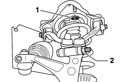
6. Unscrew the nut (2), remove the bolt and lift up both suspension arms.
Caution: Do not enlarge the groove in the wheel bearing housing with a chisel or similar tool.
7. Protect the steering rod cover with a casing (1) from damage. AUDI service stations use protective casing No.893 512 137 for this purpose.
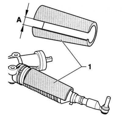
8. A strip of size A = 20 – 25 mm must be cut out of the protective shell. Carefully remove chamfers from sharp surfaces. The shell cutout must face downwards during installation.
9. Place a garage jack under the pivot support, placing a wooden shim so that the suspension does not drop too low after disconnecting the shock absorber strut. Otherwise, the lower arm hinges may be damaged
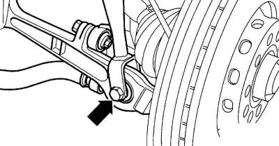
10. Unscrew the bolt (arrow on the accompanying illustration) and fold the wheel bearing housing aside.
11. Loosen the coolant expansion tank reservoir.
12. Remove the water collection compartment cover.
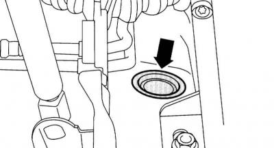
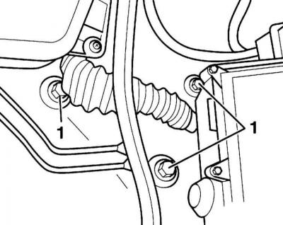
13. Remove the cover (arrow on the accompanying illustration) bolt.
14. Remove the bolts (1) in the water collection compartment.
15. Remove the shock absorber strut with the support.
Caution: When doing this, be careful not to damage the protective shell.
Installation
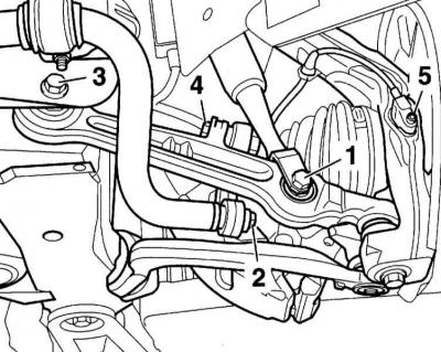
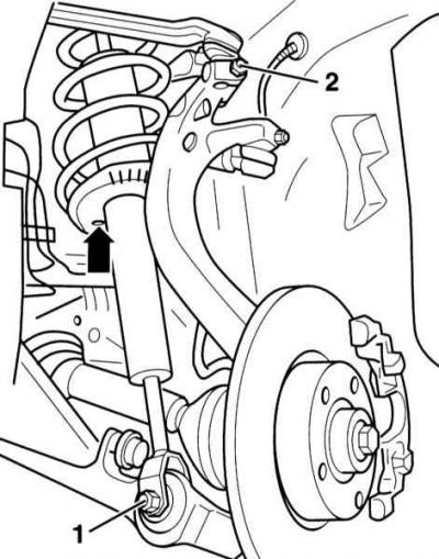
1. Insert the shock absorber strut with the support body into the support. Tighten the mounting bolt (1).
Warning: Make sure the washers are positioned correctly.
2. Rubber-metal supports have a limited range of twisting. Therefore, tighten the bolt connections on the levers when the car is standing on its wheels.
3. Insert the shock absorber strut tip into the suspension arm, lightly tighten the new connection nut (1). After lowering the car onto the wheels, tighten the nut to the torque 90Nm.
Warning: The bolt must be inserted against the direction of travel.
4. Insert both upper control arms. Press the control arm pivots down as far as possible and tighten the new nut (2) to the torque 40Nm.
5. Remove the protective shell from the case.
6. Insert the ABS electrical wire into the holder on the caliper.
7. Install the brake disc, secure the caliper, refer to Section Removal and installation the brake disc/caliper.
Warning: For vehicles with adjustable headlight range, the vehicle level sensor connecting rod must be installed on the support arm.
8. Secure the wheels, observing the direction of their rotation, lower the car onto the wheels. Only then tighten the wheel mounting bolts with a torque of 120Nm.
9. Tighten the shock absorber strut mounting bolts at the bottom to torque 90Nm with the car standing on the ground.
Models with HP-2 support
1. Loosen the bolt (2) and remove the brake pipe holder.
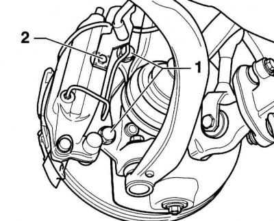
2. Loosen the mounting bolts (1) and remove the caliper.
3. Reinstall the brake pipe holder. Screw in and tighten the bolt (2).
4. Secure the support to the hanger with wire so that the weight of the support does not cause deformation and thus damage to the pipeline.
This article was copied from the website: AUDIMANUAL