
Table of contents: Warning triangle ↓ Fire extinguisher ↓ Tool kit, tire repair kit and spare… ↓ Serial spare tire ↓ Compact spare tire (emergency wheel) ↓ Anti-skid chains ↓ Wheel replacement ↓ Full size wheel caps ↓ Decorative wheel caps ↓ Wheel bolts with caps ↓ Loosening and tightening wheel bolts ↓ Wheel dismantling and mounting ↓ Directional tread tires ↓
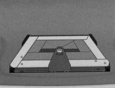
The first aid kit can be stored in the rear seat divider armrest.

To access the first aid kit, pull the handle up. The maximum load capacity of the niche is 0.5 kg.
Warning triangle
To remove the warning triangle, turn the quick release in the direction of the arrow and push the holder down.
Only a specially designed emergency stop sign, which is included in the range of original car accessories, can be placed in the trunk lid.
Fire extinguisher
The factory-fitted fire extinguisher is located in a holder located in the front passenger footwell.
Removal the fire extinguisher
1. Press the button marked "PRESS" (arrow) to release the fire extinguisher belt.
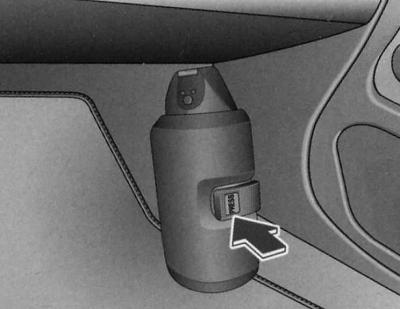
2. Remove the fire extinguisher from the holder.
Fire extinguisher mount
1. Place the fire extinguisher in the holder.
2. Secure the fire extinguisher with a belt.
After using a fire extinguisher
1. Refill and check the fire extinguisher.
Please read the instructions for using the fire extinguisher in advance. The instructions are printed on the fire extinguisher.
To keep the fire extinguisher in constant readiness for use, regularly (at the latest every two years) have the fire extinguisher checked by a specialist company or the fire department.
When purchasing a new fire extinguisher, make sure it fits the holder.
Warning: Check the expiration date of the fire extinguisher. Using an expired fire extinguisher will not provide the required extinguishing efficiency.
Tool kit, tire repair kit and spare tire
Tool kit and jack
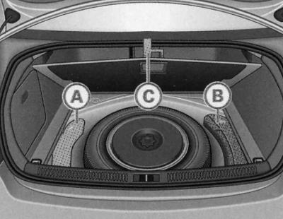
The tool kit (A) and jack (B) are located under the trunk flooring.
1. Lift the deck by the plastic handle.
2. Hang the flooring using the handle (C) on the luggage compartment seal.
3. Unlock the tool box by pulling up on the box handle.
4. Remove the tool kit or jack.
5. Return the flooring to its place and only then close the trunk lid.
The tool kit includes the following tools:
- wire grip for full-size*/decorative wheel covers;
- plastic clamp for removing protective caps of wheel bolts*;
- wheel wrench;
- safety pin for wheel replacement;
- screwdriver with adjustable rod;
- towing eye.
Before placing the jack down, return the lifting arm to its original lower position.
Some of the listed items are included in the kit only for certain modifications or are installed to order.
Tire Repair First Aid Kit
The tire repair kit is located under the trunk flooring.
The tire repair kit includes a sealant for sealing tire damage, as well as a compressor for inflating the tire. They allow you to reliably seal tire damage caused by foreign objects up to about 4 mm in diameter. In this case, the foreign body may remain in the tire.
The instructions for using the sealant and compressor can be found on the sealant bottle and the compressor body, respectively.
Steel spare tire
The steel spare wheel is located in a recess under the boot flooring. It is intended for short-term use only.
Removal the spare tire
1. Lift the deck by the plastic handle.
2. Hang the flooring using the handle on the luggage compartment seal.
3. Unscrew the handle by turning it counterclockwise.
4. Remove the spare tire.
5. Return the flooring to its place and only then close the trunk lid.
Laying down a faulty wheel
1. Place the wheel in the spare wheel well.
2. To secure the wheel, screw the handle in by turning it clockwise.
3. Return the flooring to its place and only then close the trunk lid.
Your vehicle may be equipped with a steel spare wheel at the factory. Due to the design (wheel/tire size, rubber composition, tread pattern, etc.) the spare tire, as a rule, does not correspond in its operating parameters to the serial tires of the car. Therefore, you should remember the following restrictions:
The steel spare wheel is only permitted for use on your vehicle model. It can only be mounted on your vehicle.
When installing a steel spare wheel, the driving characteristics of your vehicle will change.
The steel spare wheel is intended for short-term mounting only in the event of a flat tire. Replace the steel spare wheel with a standard wheel and serial tire as soon as possible.
If the tyre size of the steel spare wheel is different from the standard tyre, under certain circumstances snow chains cannot be fitted to the spare wheel.
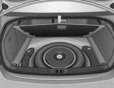
Serial spare tire
The spare wheel is located in a recess under the trunk flooring.
Removal the spare tire
1. Lift the deck by the plastic handle.
2. Hang the flooring using the handle on the luggage compartment seal.
3. Unscrew the handle by turning it counterclockwise.
4. Remove the spare tire.
5. Return the flooring to its place and only then close the trunk lid.
Laying down a faulty wheel
1. Place the wheel in the spare wheel well.
2. To secure the wheel, screw the handle in by turning it clockwise.
3. Return the flooring to its place and only then close the trunk lid.
Vehicles exported to some countries are equipped with a lighter, compact emergency wheel* instead of a wheel with a standard tyre.
Spare tire with directional tread pattern
If a directional tread pattern wheel is used as a spare tire, the following must be remembered:
- The direction of rotation of the wheel is determined by a mark in the form of an arrow applied to the sidewall of the tire.
- If, in the event of a puncture, the spare tire has to be installed in the opposite direction to the direction of travel determined by the tread pattern, then this measure should only be temporary, since the tire in this case cannot fully realize its inherent optimal driving characteristics, such as lack of tendency to aquaplaning, noiselessness and wear resistance. We especially recommend remembering this in wet weather, proportioning the speed of movement to the condition of the roadway.
Compact spare tire (emergency wheel)
The compact spare (emergency) wheel is located in a niche under the trunk flooring.
Using the emergency wheel
The emergency wheel is only intended to get you to the workshop in an emergency. Therefore, replace it with a wheel with a standard tire as soon as possible.
There are some restrictions on the use of the emergency wheel. The emergency wheel cannot be used on other models of vehicles.
Standard or winter tires must not be mounted on the emergency wheel rim.
Anti-skid chains
For technical reasons, it is not permitted to fit anti-skid chains to the compact emergency wheel.
Therefore, if you need to drive with anti-skid chains in case of a "puncture" of the front wheel, put the emergency wheel back. In turn, put anti-skid chains on the removed rear wheel and install it in place of the faulty front wheel.
Wheel replacement
Changing a wheel requires some preliminary preparation.
1. Stop on a level surface and, if possible, away from traffic.
2. Disembark all passengers and ensure that they are out of the danger zone (for example, on the outside of a road barrier).
3. Apply the handbrake fully.
4. Engage first gear (manual transmission) or set the automatic transmission selector lever to the "P" position.
5. When driving with a trailer: disconnect the trailer from the vehicle.
6. Remove the tool kit and spare wheel from the trunk.
Warning: If the road surface is sloping, additionally place a stop under the opposite wheel.
Warning: Observe the traffic regulations.
Wheel replacement
The process of changing a wheel includes the following steps.
1. Remove the wheel cap. See also "Decorative wheel caps" or "Wheel bolts with caps" below.
2. Loosen the wheel bolts.
3. Raise the car.
4. Remove/install the wheel.
5. Lower the vehicle.
6. Tighten the wheel bolts using a lug wrench in a cross pattern.
7. Replace the cap.
Operations after changing a wheel
After replacing a wheel, a number of operations must be performed.
1. Place the removed wheel in the spare wheel well and secure it.
2. Put the tool kit back in place.
3. Check the air pressure of the installed spare tire immediately.
4. Check the tightening torque of the wheel bolts with a torque wrench. The standard torque is specified in Specifications.
5. Replace the faulty wheel as soon as possible.
Warning: If the wheel bolts are rusted or tight when changing a wheel, they should be replaced before checking the tightening torque. To be careful, drive only at moderate speeds before checking the tightening torque.
Full size wheel caps
To access the wheel bolts, remove the full-size hubcaps.
Removal
1. Remove the full-size cap by hand.
Installation
1. First press the full-size cap onto the disc at the valve cutout. Then fix the full-size cap around the entire circumference of the steel disc.
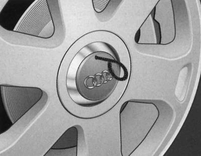
Decorative wheel caps
To access the wheel bolts, remove the decorative caps.
Removal
1. Insert the wire grip included in the tool kit into the hole in the decorative cap.
2. Pull and remove the decorative cap.
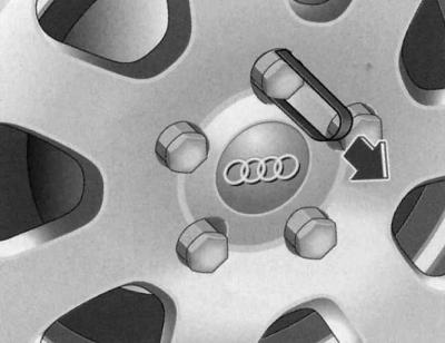
Wheel bolts with caps
Remove the caps before loosening the wheel bolts.
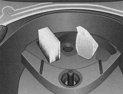
Removal
1. Slide the plastic clip supplied with the tool onto the cap until the internal tabs of the clip snap into the flange of the cap.
2. Remove the cap using the plastic clip included in the tool kit (arrow).
Installation
1. Place the caps on the bolts.
Caps are used to protect wheel bolts.
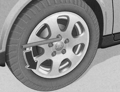
Loosening and tightening wheel bolts
Loosen the wheel bolts and only then raise the car.
Weakening
1. Place the wheel brace onto the wheel bolt until it stops.
2. Loosen the wheel bolt approximately one turn to the left (arrow), while holding the wrench handle as close to its end as possible.
Tightening
1. Place the wheel brace onto the wheel bolt until it stops.
2. Tighten the wheel bolt by turning the wheel wrench clockwise, keeping the handle of the wrench as close to the end as possible.
Warning: The Allen key in the handle of the wrench must not be used to loosen or tighten the wheel bolts. Press gently with your foot on the edge of the handle of the wrench if the bolt does not budge. Make sure you are in a stable position and hold on to the vehicle.
Wheel dismantling and mounting
Dismantling or mounting a wheel involves certain stages.
After loosening the wheel bolts and jacking up the vehicle, replace the wheel in the following order:
Wheel removal
1. With the hexagon of the screwdriver handle (from the tool kit) remove the highest wheel bolt and place it on a clean surface.
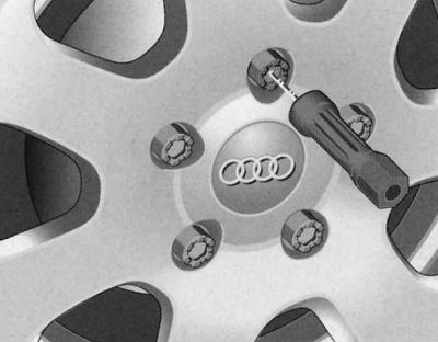
2. Screw the safety pin included in the tool kit into the freed hole by hand.
3. Then unscrew the remaining bolts as described above.
4. Remove the wheel. The safety pin remains in the hole.
Wheel mounting
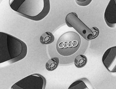
1. Place the spare tire through the safety pin.
2. Screw in the wheel bolts using the Allen key of the screwdriver handle and tighten them slightly.
3. Unscrew the safety pin and also tighten this wheel bolt slightly.
Wheel bolts should be clean and thread free. Check the mating surface of the wheel and hub. Remove any dirt from these surfaces before mounting the wheel.
The internal hexagon in the screwdriver handle makes it easier to screw in and out the wheel bolts. The screwdriver's adjustable rod must be removed for this purpose.
When installing wheels with a directional tread pattern, do not forget about the direction of rotation of the wheel.
Warning: Do not use the Allen key in the screwdriver handle to loosen or tighten wheel bolts.
Directional tread tires
Tyres with a directional tread pattern must be mounted taking into account the direction of rotation.
The direction of rotation of the wheel is determined by a mark in the form of an arrow applied to the sidewall of the tire. Be sure to follow the specified direction of rotation. Only in this case will it be possible to realize the optimal qualities of these tires, such as lack of tendency to aquaplaning, noiselessness and wear resistance.
Installing a spare tire in the opposite direction to the direction of travel determined by the tread pattern in the event of a puncture requires caution when driving, since the tire in this case cannot fully realize its inherent optimal qualities.
We especially recommend that you remember this in wet weather, adjusting your speed to the condition of the roadway.
To take full advantage of the directional tread pattern, replace the damaged tire as soon as possible to restore proper rotation direction of all tires.
Text provided by the online resource audimanual.ru