
Table of contents: Operating instructions ↓ Towable load weight ↓ Cargo placement ↓ Tire pressure ↓ Exterior mirrors ↓ Headlights ↓ Removable ball head ↓ Driving instructions ↓ Load distribution ↓ Speed ↓ Overheat ↓ Removable towing hitch ↓ Use of attachments/accessories on… ↓ Removal the ball head ↓ Attachment points for towing hitch ↓
The factory equipment of the vehicle with a towing hitch also provides everything necessary for operating the trailer in accordance with technical and regulatory requirements.
The vehicle is equipped with a 13-pin plug for the electrical connection between the vehicle and the trailer. If the trailer has a 7-pin plug, the corresponding adapter cable available from Audi can be used.
The additional installation of a towing hitch must comply with the requirements of the manufacturer of this device.
Operating instructions
Please be aware of the maximum towing capacity, see. Specifications.
Towable load weight
Never exceed the maximum towing capacity.
If the maximum permissible trailer weight is not fully utilized, then it is possible to overcome climbs with a greater incline.
Standard values for the mass of towed cargo are valid only at altitudes up to 1000 m above sea level. As altitude increases, the rarefaction of the air increases and, accordingly, the engine power decreases and, as a result, the ability to overcome climbs. Therefore, the standard mass of the road train is reduced by 10% for every 1000 m of ascent. The mass of the road train is equal to the sum of the masses (loaded) car and (loaded) trailer.
The trailer load data on the trailer identification plate are reference values. Data that may be lower than these values can be found in the vehicle registration documents or in the Specifications.
Cargo placement
Distribute the trailer load so that the heaviest items are located as close to the trailer axle as possible. Also, secure the load to prevent it from shifting while driving.
Use as much of the permissible support load transmitted to the ball head via the trailer drawbar as possible, but do not exceed it.
Tire pressure
Set the vehicle's tire pressure to the correct level for its full load, see the tire pressure label on the door pillar. If necessary, also adjust the trailer tire pressure according to the trailer manufacturer's recommendations.
Exterior mirrors
If the standard rearview mirrors do not provide sufficient rear visibility, additional outside mirrors must be installed. Both outside mirrors must be mounted on folding brackets. Adjust the position of the mirrors so that sufficient rear visibility is provided.
Headlights
Before driving with a trailer, check and, if necessary, adjust the headlight setting using the headlight range adjustment device, see. Lighting and visibility.
Removable ball head
The factory-fitted removable ball head of the towing hitch is located in the spare wheel well of the luggage compartment, along with the installation instructions.
Driving instructions
Driving with a trailer requires special care.
- Do not tow a loaded trailer with an unloaded vehicle.
- Do not drive at maximum speed, especially when driving downhill.
- Brake in a timely manner.
- When the outside temperature is high, watch the coolant temperature indicator.
Load distribution
When the vehicle is empty and the trailer is loaded, the load distribution is extremely unfavourable. If movement is necessary in this case, the movement must be especially slow.
Speed
As the speed increases, the dynamic properties of the road train deteriorate. Therefore, in unfavorable road, weather and aerodynamic conditions, do not use the maximum speed permitted by the traffic rules. This is especially true when driving downhill.
Reduce speed immediately at the slightest sign of trailer wobbling. Never try to "straighten out" the road train by increasing speed.
Brake in good time! When towing a trailer with an inertial braking system, brake softly at first and then smoothly. This will help avoid jolts from the locked trailer wheels. To use the engine braking capability, shift down to a lower gear in good time.
Stabilizing devices reduce trailer oscillations relative to the transverse axis and its wobbling. It is recommended to use them for trailers with a significant mass.
Overheat
Monitor the coolant temperature indicator when the outside temperature is very high and when driving up a long hill in low gear and at high engine speed, see. Controls and instruments. When the pointer enters the right part of the scale, immediately reduce the speed. When the signal lamp on the instrument panel flashes, stop and cool the engine by letting it idle for a few minutes.
Removable towing hitch
Installation and removal of the towing hitch requires precision.
The removable ball head of the towing hitch is located under the luggage compartment flooring.
- Cars with a spare wheel.
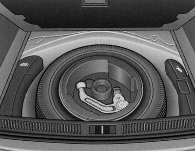
Luggage compartment: spare wheel with towing hitch
- Cars with a tire repair kit.
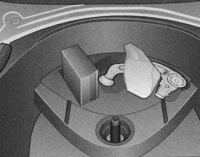
Trunk: tire repair kit and towing hitch
To install and remove the ball head, normal muscular effort of the hands is sufficient.
Use of attachments/accessories on the towing hitch
Please note that if you use unsuitable attachments mounted on the towing hitch, (for example, a bicycle rack), there may be hidden damage to the ball head, which in extreme cases may lead to the destruction of the towing hitch when towing a trailer.
Warning: Before each ride, check that the ball head is properly secured.
Never release the ball head when a trailer is attached.
When driving without a trailer, remove the ball head and check that the cover of the mounting socket is closed correctly.
When cleaning a vehicle with a steam jet pump, first remove the ball head and check that the mounting socket is closed correctly with the cover.
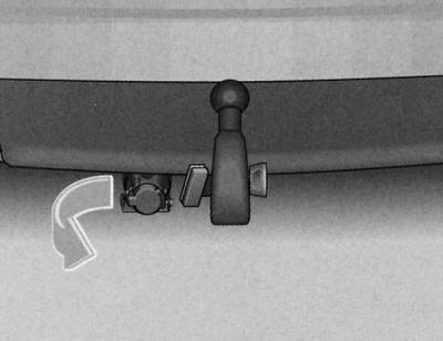
Ball head installation (first stage)
1. Under the bumper, open the cover of the mounting socket completely. The cover is automatically fixed in this position.
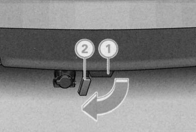
2. Check the mounting socket for contamination and clean it if necessary.
Ball head installation (second stage)
The ball head must be clean and undamaged.
1. Check for contamination and damage to the retainer (A), release pin (B), ball head housing where it contacts the mounting pipe, and flywheel.
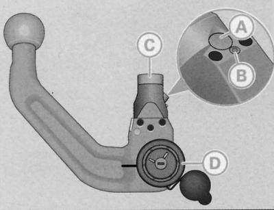
The ball head must be mounted with preload
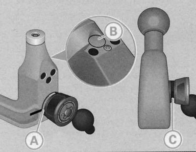
Removable towing hitch: ball head with housing
Preload is ensured by fulfilling the following conditions:
- The red mark on the flywheel is located in the area of the black mark on the ball head housing.
- The retainer (B) is recessed into the hole in the ball head housing.
- The handle, which is clearly visible visually, is located at a certain distance from the ball head body, so that there is a gap (C) between the handle and the ball head body.
The ball head can only be installed with pre-tension.
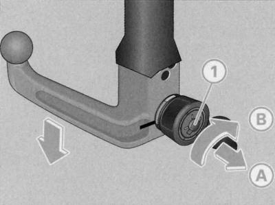
Ball head installation (third stage)
Ball head tension (if necessary):
1. Insert the key (1) into the flywheel lock and turn it in the direction of the red mark.
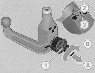
2. Pull the handle in the direction of the arrow (A) and then turn it in the extended position in the direction of the arrow (B) until the lock (2) is locked and the release pin (3) is visibly extended.
Installing the ball head:
1. Install the ball head with tension into the mounting socket and press it upwards in the direction indicated by the arrow. The fixation process is carried out automatically. A click should be clearly heard.
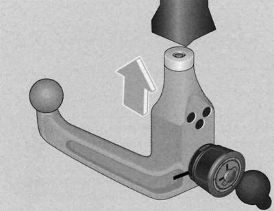
2. Lock the ball head by turning the key in the direction of the green mark.
3. Remove the key.
Mounting the head (fourth stage)
Checking the reliability of the fastening:
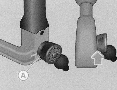
Removable towing hitch: checking the reliability of the fastening
Correct fastening is ensured by fulfilling the following conditions:
- The green mark (A) of the flywheel is located in the area of the black mark of the ball head housing.
- The handle fits tightly against the ball head housing. As a result, there is no gap between the handle and the ball head housing -arrow-.
- The ball head is locked and the key is removed (the handle does not extend).
- The ball head sits securely in the mounting socket (check by moving it with your hand).
Trailer socket:
1. To connect the trailer cable to the vehicle, move the vehicle's power socket located under the bumper downwards in the direction of the arrow.
If the above conditions are not met, repeat the installation.
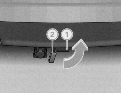
Removal the ball head
1. Insert the key into the flywheel lock (1).
2. Unlock the ball head (turn the key to the red mark).
3. Hold the ball head body firmly and pull the handle in the direction of the arrow (A).
4. Turn the handle in the extended position until it stops in the direction of the arrow (B).
5. Release the handle. It is fixed by itself with tension.
6. Pull the ball head downwards out of the mounting socket (1). The mounting socket is then automatically closed by cover 0.
7. Place the ball head under the trunk flooring.
8. Move the socket upward.
Attachment points for towing hitch
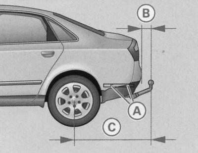
Attachment points: side view
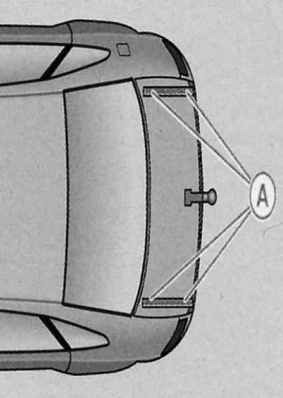
Attachment points: top view
The four attachment points (A) of the towing hitch are located on the underside of the vehicle.
The minimum distance (B) between the bumper and the ball head must be 65 mm. The distance (C) between the rear axle and the ball head must be 1056 mm.