
Table of contents: Ball head installation ↓ Towing hitch (post-factory… ↓
Installation and removal of the towing hitch requires precision.
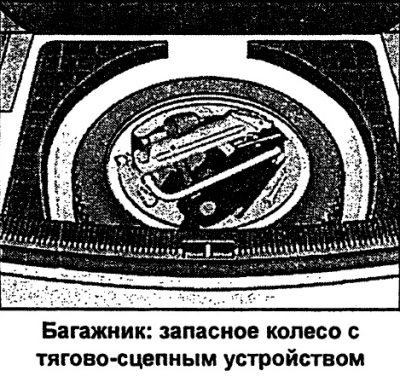
The removable ball head of the towing hitch is located in the spare wheel well.
To install and remove the ball head, normal muscular effort of the hands is sufficient.
Attention
- Before each trip, check that the ball head is correctly secured.
- Never release the ball head when a trailer is attached,
- When driving without a trailer, remove the ball head and place it in the spare wheel well. Install the plug in the mounting pipe.
- When cleaning a car with a steam jet pump, first remove the ball head and install a plug in the mounting pipe.
Ball head installation
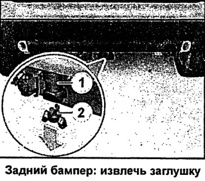
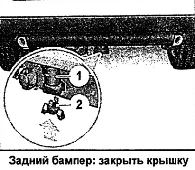
- Remove plug 2 from mounting pipe 1 under the bumper.
- Check for contamination of the mounting pipe and clean it if necessary.
The ball head must be clean and undamaged
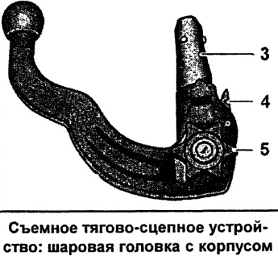
- Check for contamination and damage to the ball head housing at the point of contact with the mounting pipe 3, the release pin 4, and the flywheel 5.
The ball head must be mounted with preload
Preload is ensured by fulfilling the following conditions:
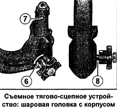
- The red mark 6 of the flywheel is located in the green field area of the ball head housing.
- The 7 head clamps are recessed into the holes in the ball joint housing
- The flywheel, which is clearly visible visually, is located at a certain distance from the ball head housing, so that there is a gap of 8 between the flywheel and the ball head housing.
The ball head can only be mounted with pre-tension.
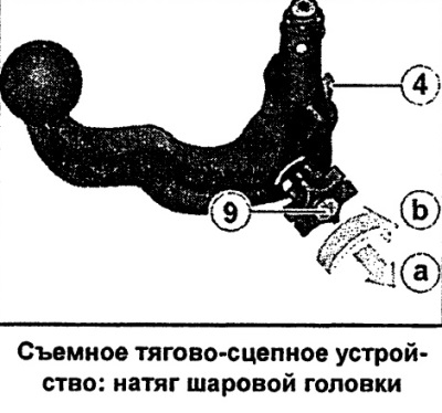
Ball head tension (if necessary)
- To lock the ball head, insert the key supplied in the delivery set into the handwheel lock 9 and turn it to the right.
- Pull the handwheel in the direction of arrow a and then turn it in the extended position in the direction of arrow b until the release pin 4 is locked.
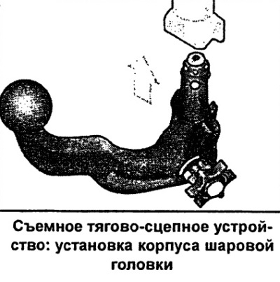
Installing a ball head
- Install the ball head with tension into the mounting pipe and press upwards in the direction indicated by the arrow. The fixation process is carried out automatically. A click should be clearly heard.
- Lock the ball head by turning the key to the left and put the cap on the lock.
- Remove the key.
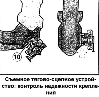
Checking the reliability of fastening
Correct fastening is ensured by fulfilling the following conditions:
- The green mark 10 of the flywheel is located in the green field area of the ball head housing.
- The flywheel is adjacent to the ball head housing. As a result, there is no gap between the flywheel and the ball head housing -arrow-.
- The ball head is locked and the key is removed (the flywheel does not extend).
- The ball head fits securely into the mounting tube (check by moving it with your hand).
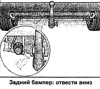
Trailer socket
- To connect the trailer cable to the vehicle, move the vehicle's power socket located under the bumper downwards in the direction of the arrow.
If the above conditions are not met, repeat the installation.
Removal the ball head
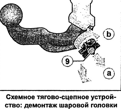
- Remove the cap and insert the key into the lock 9 of the handwheel.
- Unlock the ball head (turn the key to the right).
- Pull the handwheel out in the direction of the arrow and then turn it in the pulled out position until it stops in the direction of the arrow.
- Hold the handwheel firmly and remove the ball head from the mounting tube.
- Release the flywheel. It is fixed by itself with tension.
- Put the cap on the key.
- Place the ball head in the spare wheel well.
- Move the socket upwards.
- 3 Install the plug on the fastening pipe 1.
Once the wide head is removed, the key cannot be removed, thus preventing loss of the key.
Towing hitch (post-factory installation)
Attachment points for towing hitch
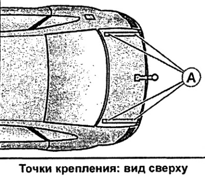
The four attachment points A of the towing hitch are located on the underside of the vehicle.
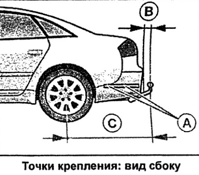
The minimum distance B between the bumper and the ball head must be 65 mm. The distance C between the rear axle and the ball head must be 1155 mm.