
Table of contents: Central console ↓ Dashboard ↓ Coolant temperature gauge ↓ Tachometer ↓ Digital watch with date indication ↓ Radio clock ↓ Instrument lighting ↓ Speedometer, trip meter and odometer ↓ Fuel gauge ↓ SNECK button ↓ Indication of maintenance period ↓ Reset button ↓ Instrument panel warning lights ↓ Cars with gasoline engines ↓ Diesel Engine Cars ↓
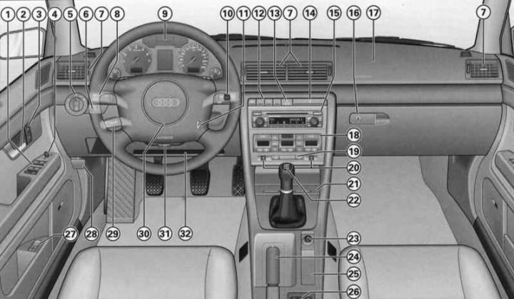
- (1) - Electric windows (Unlocking and locking the car)
- (2) - Door handle
- (3) - Single control lock system switch (Unlocking and locking the car)
- (4) - Electric adjustment of exterior mirrors (Lighting and visibility)
- (5) - Light switch (Lighting and visibility)
- (6) — Headlight range control (Lighting and visibility) - function of illumination of the road to the house/to the car (Lighting and visibility)
- (7) - Deflectors with a ribbed regulator (Heater, ventilation and air conditioning)
- (8) — Lever switch for direction indicators and high beam (Lighting and visibility)
- (9) - Instrument panel
- (10) - Lever switch:
- windshield wiper and windshield washer (Lighting and visibility)
- trip computer controls (Driver Information System (FIS))
- (11) — Ignition switch (Features of operation and auxiliary systems)
- gasoline engine
- diesel engine
- (12) — Depending on the configuration:
- pencil case (Seats and niches)
- electronic Skid Control (ESP) Switch (Features of operation and auxiliary systems)
- sunshade drive switch (Lighting and visibility)
- acoustic parking assistance switch (Features of operation and auxiliary systems)
- (13) — Hazard warning light switch (Lighting and visibility)
- (14) - Cup holder (Seats and niches)
- (15) — Depending on the configuration:
- radio
- navigation system plus (navigation, radio, CD changer, TV/video)
- (16) - Lockable storage compartment (Seats and niches)
- (17) — Front passenger airbag (Security systems)
- (18) — Depending on the configuration:
- air conditioner (Heater, ventilation and air conditioning)
- heating and ventilation (Heater, ventilation and air conditioning)
- (19) — Rear window heating switch (Lighting and visibility)
- (20) — Seat heating regulator (Heater, ventilation and air conditioning)
- (21) - Ashtray (Seats and niches)
- (22) — Gear shift/selector lever:
- manual transmission
- 5-speed automatic transmission (Automatic transmission (AT))
- Multitronic (Automatic transmission (AT))
- (23) — Cigarette lighter/socket (Seats and niches)
- (24) - Handbrake (Features of operation and auxiliary systems)
- (25) — Depending on the configuration:
- niche
- navigation system controls
- menu indication controls (Driver Information System (FIS))
- (26) — Depending on the configuration:
- compartment
- niche for storing audio cassettes (Seats and niches)
- fax and computer connector (Communication and navigation)
- (27) — Driver's seat memory keys (Seats and niches)
- (28) - Hood release handle
- (29) - Tempostat handle (Features of operation and auxiliary systems)
- (30) - Steering wheel with:
- sound signal
- driver's airbag (Security systems)
- radio system controls (Communication and navigation)
- controls of the radio system and telephone (Communication and navigation)
- (31) - Adjustable steering column (Features of operation and auxiliary systems)
- (32) - Niche for storing a folder with documents (Seats and niches)
Warning: If your vehicle is factory-equipped with a radio or navigation system, the corresponding operating instructions are included with it.
The location of some controls on right-hand drive vehicles differs from that shown in the illustration. However, the symbols used to identify them correspond to those on left-hand drive vehicles.
Central console
Warning: Some of the items listed are only included in certain models or are optional extras.

Driver's position: center console
- A - Row of switches
- B — Audi navigation system plus/audio system, e.g. Audi symphony
- C — Air conditioning and heated glass/seat switches (Heater, ventilation and air conditioning)
The location of some controls on right-hand drive vehicles differs from that shown in the illustration. However, the symbols used to identify them correspond to those on left-hand drive vehicles.
If your vehicle is factory-equipped with the Audi navigation plus system and the Audi symphony radio system, the corresponding operating instructions are included.
The Audi navigation system plus includes radio, CD player and TV* functions.
Dashboard
The instrument panel serves as the driver's information center for the vehicle.
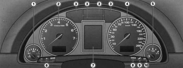
- 1 — Coolant temperature gauge
- 2 - Tachometer with digital clock and date display
- 3 - Control lamps
- 4 - speedometer with counter and mileage meter display
- 5 — Fuel gauge
- 6 - Setting buttons
- - digital clock and date
- - lighting of devices
- 7 — Display
- - indication of the maintenance period
- - driver information system
- 8 — CHECK button
- 9 — Maintenance due date indicator button
- 10 — Trip meter reset button
When the ignition is on, the instrument panel arrows light up.
When the light is on, the scales are additionally illuminated.
Coolant temperature gauge
The coolant temperature gauge only works when the ignition is on. To avoid engine damage, please note the following temperature instructions.
Cold Engine Temperature Range
If the needle is still on the left side of the scale, it means that the engine has not yet reached operating temperature. Avoid high revs, "full throttle" and significant engine load.
Operating temperature
The engine has reached operating temperature when the temperature gauge needle is within the middle of the scale during normal driving. Under significant engine load and high outside temperatures, the needle may move further to the right on the scale. This should not be a cause for alarm until the warning symbol lights up on the instrument panel display
Flashing of the signal symbol on the display indicates a drop in the coolant level or its overheating, see. Driver Information System (FIS).
Warning: Additional headlights and other add-on components that obstruct the supply of cooling air impair the cooling effect of the coolant. In high outside temperatures and significant engine loads, there is a risk of engine overheating!
One of the tasks of the front spoiler during movement is the correct distribution of cooling air. If the spoiler is damaged, the cooling effect is reduced and there is a risk of engine overheating! Use qualified assistance.
Tachometer
The tachometer shows the engine crankshaft rotation speed.
At a rotation speed of less than 1500 rpm, you should switch to the next lower gear. The beginning of the red sector of the scale corresponds for all gears to the range of maximum revolutions that are permissible for a short-term running-in and warmed-up engine. You should switch to a higher gear, set the selector lever to the position "D" or reduce the gas until the arrow reaches this sector of the scale.
Warning: Only a short-term entry of the tachometer needle into the red sector of the scale is permitted - there is a risk of engine damage! The start of the red scale depends on the engine version.
Warning: Shifting into higher gears early will help you save fuel and reduce operating noise!
Digital watch with date indication
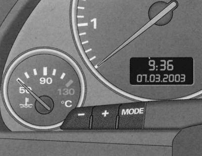
Fragment of the dashboard:
- digital clock
- indicator panel with radio clock reception symbol, time and date
- instrument lighting control buttons
The car is equipped with a quartz clock or a radio clock.
Setting the clock
1. Press the button; the hour indication is flashing.
2. The hour indication is increased by pressing the (+) button.
3. The hour indication decreases by pressing the (-) button.
Setting the minutes
1. Press the button as often as necessary until the minute indication starts flashing.
2. The minutes display is increased by pressing the (+) button.
3. The minutes display is reduced by pressing the (-) button.
Setting the calendar date
1. Press the button as often as necessary until the day indication starts flashing.
2. The day indication is set by pressing the (+) or (-) button.
3. Press the button again. Now the month indication flashes.
4. The month indication is set by pressing the (+) or (-) button.
5. Press the button again. Now the year indication flashes.
6. The year indication is set by pressing the (+) or (-) button.
Turn off calendar date
1. Press the button repeatedly until the full calendar date display starts flashing.
2. The date indication is removed by pressing the (-) button.
Calling a calendar date
1. Press the "MODE" button as often as necessary until the full calendar date indication starts flashing.
2. The date display is called up by pressing the (+) button.
When the indicator stops flashing after pressing the button, the installation process and time/date programming are complete.
By pressing the CHECK button with the ignition off, you can turn on the digital clock with date display and mileage counter for a few seconds.
Radio clock
In the "radio-controlled quartz watch" mode, a radio information reception symbol appears on the indicator panel (radio tower with diverging waves). In this mode, manual change of the minute and date indication is not possible.
In different time zones, it is necessary to manually change the clock display accordingly.
If there is no corresponding radio signal for three days, the watch automatically switches to the "quartz watch" mode. In this case, the indication of the radio information reception symbol disappears. If you need to re-set the time and calendar date, refer to the Digital watch with date indication subsection.
Instrument lighting
1. To increase the background brightness, press the (+) button.
2. To decrease the background brightness, press the (-) button.
A phototransistor installed in the instrument panel controls the instrument lighting (illumination of arrows and scales), central console lighting and display lighting.
When the lights are off and the ignition is on, the instruments are illuminated (arrows and scales). As the ambient brightness decreases, the instrument lighting automatically decreases. When the ambient light is low, the lighting is switched off completely. This function serves as a reminder for the driver to switch on the low beam in a timely manner when the ambient brightness decreases.
Speedometer, trip meter and odometer
Speedometer
The speedometer shows the speed.
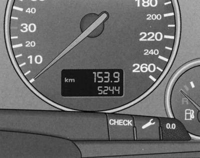
Fragment of the instrument panel: counter and mileage meter, CHECK button
Mileage indication is displayed in kilometers (km). In some modifications, indication is displayed in miles.
Total mileage counter (is located below)
Records the total mileage of the vehicle in kilometers or miles.
Odometer (is located on top)
Registers the mileage since the last reset. It allows you to measure specific segments of the mileage. The division value of the meter is 100 m or 1/10 mile. Reset (setting the value to zero) is carried out by pressing the reset button.
Malfunction indication
The presence of a malfunction in the instrument panel is indicated by the "dEF" indicator on the odometer display.
Fuel gauge
The indicator only works when the ignition is on.
The fuel tank capacity is given in the Specifications. When the pointer reaches the reserve field, the symbol lights up on the instrument panel display, see Driver Information System (fis)
Warning: Never run out of fuel! Irregular fuel supply can cause misfires in the ignition system. As a result, unburned fuel will enter the exhaust system. This can lead to overheating and damage to the catalytic converter
SNECK button
Functional purpose of the CHECK button:
Turning on the digital clock, counter and odometer display
By pressing the CHECK button with the ignition off, the digital clock display with date indication and mileage displays are turned on for a few seconds.
Enabling the Vehicle Malfunction Monitoring System function (AutochekControl)
With the ignition on and while driving, the automatic fault monitoring system, see. Driver Information System (FIS) continuously monitors certain functions and the technical condition of the vehicle systems.
With the ignition on, the malfunction monitoring system function can also be activated by pressing the CHECK button. The system operation can be checked with the engine off or running and at a speed of no more than 5 km/h.
Output to the display of instructions to the driver
If any of the 1st priority symbols flashes on the display, see. Driver Information System (FIS) or if an indication appears indicating a malfunction of the lamp function, see. Driver Information System (FIS), by briefly pressing the CHECK button you can turn on the lighting of the corresponding instruction to the driver again.
For example: Motor abstellen, Olstand prufen (turn off the engine, check the oil level). The display indicator goes out after approximately 5 seconds.
Speed alarm
By pressing the CHESC button while driving, the threshold value for warning level 1 of the speed alarm device can be programmed, see. Driver Information System (FIS), "Warning level 1: function". The threshold value of warning level 2* of the overspeed alarm device, see. Driver Information System (FIS), "Warning level 2: function" is only programmed when the ignition is off.
Indication of maintenance period
The service due date indicator reminds you when the next service is due.
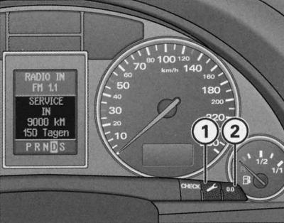
Instrument panel fragment: indication of maintenance period
Maintenance indication
By briefly pressing the button (1) with the ignition on, the number of kilometers until the next maintenance is displayed. The display can be displayed both with the engine off and running and at a speed of no more than 5 km/h. The display of the number of kilometers until maintenance is updated each time the ignition is turned on - the first time after 500 km after reset. The display of a new car/car after maintenance during the first 500 km of mileage will display the message SERVICE IN——-KM—-TAGEN.
This also applies to vehicles with "LongLifeservice".
Maintenance Reminder
When there are 2000 kilometers or less left until the next maintenance, when the ignition is turned on, the display shows:
SERVICE IN 2000 km—TAGEN
After 5 seconds, the display switches to the normal display mode. The indication of the number of kilometers to maintenance is updated every time the ignition is turned on, until the time for maintenance.
The maintenance deadline has arrived
When the time comes for the next maintenance, the display shows "SERVICE!" immediately after the ignition is turned on. After 5 seconds, the display switches to the normal display mode.
Reset to the new indication countdown position
Turn off the ignition.
With button (1) pressed, turn on the ignition. One of two messages appears on the display: "SERVICE IN——-KM" or "SERVICE".
Press the reset button (2) until the display shows "SERVICE IN——-KM—-TAGEN" or "SERVICE!".
If the reset button is not pressed within 5 seconds, the display switches to normal display mode.
Warning: Reset the display to a new count only after performing maintenance. Otherwise, it will not correspond to reality.
When the battery is disconnected, the service interval indication data is retained.
If there is a 1st priority level fault (red symbol) it is not possible to display the number of kilometers left until maintenance.
Reset button
The reset button "0.0" (2) has the following purpose:
Resetting the trip meter
Setting the trip meter (upper) to zero is done by pressing the reset button.
New maintenance due date indication countdown
This is done by pressing the reset button. In this case, the maintenance period indication must be in reset mode.
Instrument panel warning lights
Indicator lamps indicate the status of certain functions/malfunctions.
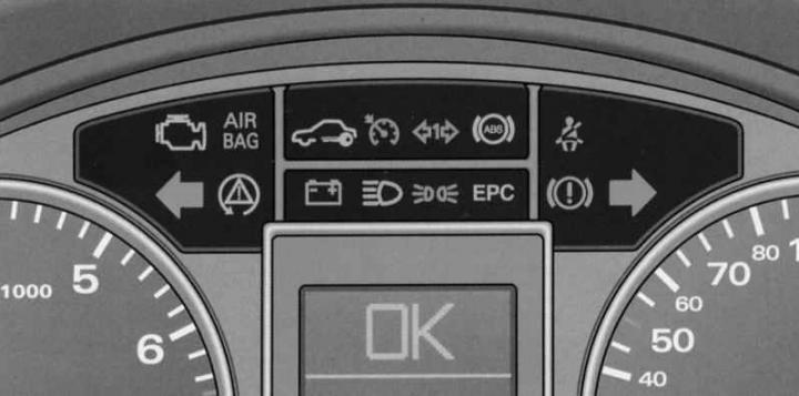
Instrument panel: indicator lights.
AIR
BAG — Security systems
EPC — Engine control (alternatively with
Warning: A number of functions are monitored by the fault monitoring system, see. Driver Information System (FIS). Functional disturbances are displayed on the instrument panel display as red symbols (priority 1 - danger) or yellow symbols (priority 2 - warning).
Engine electronics
Control lamp
AIR BAG safety systems
The control lamp monitors the operation of the airbags and seat belt tensioners.
Control lamp AIR BAG lights up for a few seconds when the ignition is turned on.
The system is faulty if the indicator lamp AIR BAG does not go out after the ignition is turned on or lights up, flashes while driving, and does not light up when the ignition is turned on.
Electronic anti-theft lock
The indicator lamp indicates the exchange of data between the vehicle and the original ignition key.
When the ignition is turned on, a request for vehicle key data is automatically made. A positive result of data exchange is confirmed by a short illumination of the control lamp
When using a non-original key, the indicator lamp starts to flash for a long time. In this case, the vehicle cannot be operated, see. Unlocking and locking the car.
Tempostat
Control lamp
Trailer direction indicators
When driving with a trailer, the indicator lamp flashes together with the direction indicators.
Control lamp
If the turn signal light on the vehicle itself or on the trailer is faulty, the indicator light does not flash.
Anti-lock braking system (ABS) device
The indicator lamp monitors the function of the ABS and the electronic differential lock (EDS).
Control lamp
The ABS device is faulty if:
- The indicator lamp does not light when the ignition is turned on.
- The indicator light does not go out after a few seconds.
- The control lamp lights up while driving.
In this case, the vehicle can only be braked using the normal braking system, i.e. without ABS. Contact a service station immediately. For more information on ABS, see. Features of operation and auxiliary systems.
If the ABS is faulty, the ESP indicator light comes on.
Malfunction of the entire brake system
If the abs control light
In the event of a functional failure of the brake system, the symbol appears on the instrument panel display
Electronic Differential Lock (EDS) Malfunction
The eds device works together with the abs. The failure of the eds device is indicated by the illumination of the abs control lamp
Fasten your seat belt reminder
The warning light reminds you that your seat belt is not fastened.
Control lamp
For more information on seat belts, see. Security systems.
Direction indicators
The indicator lamp flashes together with the direction indicators.
Depending on which direction indicators are on, the left one flashes
If one of the direction indicators fails, the indicator lamp flashes twice as fast.
This does not apply to driving with a trailer. If any of the turn signal lights on the vehicle itself or on the trailer is faulty, the indicator lamp does not flash. For more information on turn signals, see. Lighting and visibility.
Battery discharge
The control lamp signals a generator defect or a malfunction of the vehicle's electrical equipment.
Control lamp
If the lamp
Warning: Additional warning symbol lights up in the instrument cluster while driving (cooling system malfunction), cm. Driver Information System (FIS), indicates a malfunction of the water pump of the cooling system - there is a risk of engine damage! Stop immediately and turn off the engine.
High beam
The indicator lamp lights up when the high beam is on.
Control lamp
For more information on high beam, see. Driver Information System (FIS).
Parking lights
The indicator lamp lights when the parking lights are on.
Control lamp
Brake system
The indicator lamp flashes when the brake fluid level is too low, the ABS system is faulty, or the handbrake is applied.
If the indicator lamp flashes
When ABS fails, the ABS control lamp
Handbrake tightened
Control lamp
Electronic skid control system (ESP)
The control lamp monitors the function of the electronic skid control system.
Functions of the control lamp:
- The lamp flashes while driving when the ESP device is operating.
- The lamp lights up to check the function when the ignition is turned on and should go out after about 2 seconds.
- The lamp lights up when there is a malfunction of the ESP.
- The lamp lights up after disconnecting and then reconnecting the battery.
- The lamp lights up when the ESP device is switched off.
- The lamp also lights up when the ESP fails, since the ESP device works together with the ABS.
If the indicator lamp lights up immediately after starting the engine, the ESP may be switched off by the system. In this case, you can switch on the ESP by switching the ignition off and then on. The lamp goes out and the device is completely ready for use.
If the battery is disconnected and then reconnected, the indicator lamp lights up after the ignition is turned on. A short straight drive is enough to turn the lamp off.
For more information on ESP, see. Features of operation and auxiliary systems.
Cars with gasoline engines
Engine Power Control EPC
The control lamp monitors the engine management system.
EPC indicator light (Electronic Power Control) lights up for a few seconds when the ignition is turned on to demonstrate its functionality.
Warning: If the indicator lamp illuminates while driving, it indicates a fault in the engine management system. Perform the required engine checks immediately.
Diesel Engine Cars
Preheat system
When the control lamp lights up, the engine is preheated. Start the engine as soon as the lamp goes out, see. Features of operation and auxiliary systems. When starting a warm engine, as well as at an outside temperature above +8°C, the control lamp lights up for approximately 1 second.
Warning: If the glow plug indicator lamp comes on while driving, it indicates a fault in the engine management system. The engine needs to be checked immediately.
The reason why the control lamp does not light at all when the ignition is turned on may be a malfunction in the preheating system. The engine needs to be checked.
(The original publication in its entirety is posted on the website AUDIMANUAL.ru)