
Table of contents: Tire repair ↓ Preparation ↓ Filling a tire with sealant ↓ Inflating a tire ↓ Final inspection ↓ Wheel replacement ↓ Engine Starting Assistance ↓ Starting the engine ↓ Towing and towing ↓
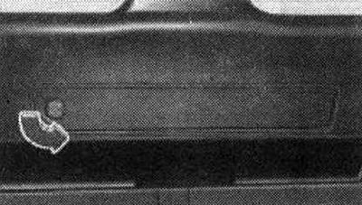
The factory-fitted warning triangle is located in the tailgate. To open the lid, turn the rotary latch and remove the lid. Remove the warning triangle from the holder. Only the warning triangle specially designed for this purpose, which is part of the original car accessories, can be placed in the tailgate. If you wish to equip your car with a warning triangle, contact Audi.
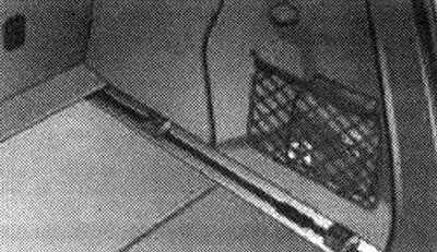
Trunk right: bandage pillow
The dressing pad is located behind the right storage net in the trunk. The storage net on the side rails can be folded down if needed.
Tire repair
Tire repair process
Trunk on the left: compressor
Preparation
In case of a puncture, stop as far away from traffic as possible. Apply the parking brake to prevent unintentional movement of the car. Engage first gear (manual transmission) or set the gearshift lever to position "P" (automatic transmission). Make sure that the tire can be repaired using a tire repair kit. Disembark all passengers and ensure that they are outside the danger zone. Remove the sealant and compressor from the trunk. Stick on a sticker with the text "max. 80 km/h", which is located together with the container with sealant, on the dashboard so that it is in the driver's field of vision.
Filling a tire with sealant
Before filling the tire with sealant, shake the container with the sealant thoroughly. Screw the included filling hose completely onto the container with the sealant. As a result, a hole automatically appears in the film of the lid. Remove the cap from the tire valve and unscrew the valve core with the included tool for unscrewing the tire valve. Place the valve core on a clean surface. Remove the plug of the filling hose and put the hose on the tire valve. Hold the container upside down and pour the entire contents of the container into the tire. Then disconnect the hose and screw the core firmly into the tire valve.
Inflating a tire
Screw the compressor filling hose onto the tire valve and insert the plug into the cigarette lighter. Pump the tire pressure from 2.0 to 2.5 bar and check it on the pressure gauge. If the specified value is not reached, slowly drive the car about 10 meters forward or backward. This helps to distribute the sealant better. If the air pressure in the tire is still below the specified value, then it is not possible to repair the tire with sealant.
Final inspection
After about ten minutes of driving, stop and check the air pressure in the tire. If the air pressure in the tire is less than 1.3 bar, the tire is too badly damaged. Further driving is prohibited! You should seek qualified assistance.
Attention. On a busy road, turn on the hazard warning lights and put up an emergency stop sign. This will protect you and other road users. Make sure that all passengers are outside the danger zone (for example, behind a road barrier). Observe the manufacturer's safety instructions on the compressor and the instructions on the sealant container! If the air pressure in the tire is less than 2.0 bar after an eight-minute inflation process, the tire is too badly damaged. Do not drive any further! If it is not possible to repair the tire with a sealant, seek qualified assistance. If the air pressure in the tire is less than 1.3 bar after 10 minutes of driving, the tire is too badly damaged. Do not drive any further. Seek qualified assistance. Do not operate the compressor continuously for more than 8 minutes. Otherwise, the compressor may overheat. In this case, let the compressor cool down and then use it again. If sealant leaks, let it dry and then remove it like a film. After repairing the tire, purchase a new container of sealant from a specialized company. The tire repair kit is then ready for use again.
Wheel replacement
Wheel replacement: removing caps
Applies to vehicles: with caps. Before unscrewing the wheel bolts, remove the caps. Push the plastic clamp included in the tool kit onto the cap. The internal clamp locks should snap into the cap flange. Remove the cap with the plastic clamp included in the tool kit.
Installation
Put the caps on the bolts. The caps serve to protect the wheel bolts.
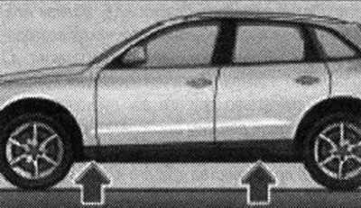
Wheel replacement: jack installation locations
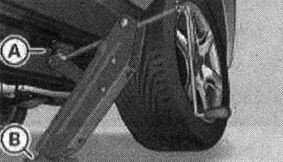
Wheel replacement: jack
To remove the wheel, lift the car with a jack. Find the jack socket on the lower side member of the body closest to the faulty wheel. Rotate the handle of the jack located under the socket and raise its lifting paw to such a height that it is directly under the vertical edge of the side member. Align the jack so that the cam catch of the lifting paw "A" covers the edge of the side member, and the movable heel "B" rests with its entire surface on the base. Raise the car by rotating the jack handle until the faulty wheel is off the ground. It is allowed to install the jack only in the places shown. Only one socket is provided for each wheel. Installing the jack in other places is prohibited. If the car is installed on an unstable surface, it may slip off the jack. Therefore, install the jack on a solid supporting surface. If necessary, install a wide, solid support under the heel of the jack. On a slippery surface (for example, facing tiles) place a non-slip mat under the jack (for example, a rubber mat).
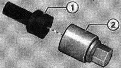
Locking wheel bolts with adapter
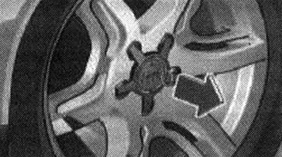
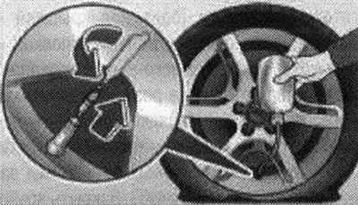
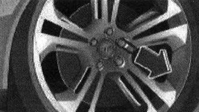
Wheel replacement: removing the decorative cap
A special adapter is required to turn the locking wheel bolts. Insert the wire grip included in the tool kit into the hole in the decorative cap. Pull and remove the decorative cap. Insert adapter "2" as far as it will go into the locking wheel bolt "1". Place the wheel brace as far as it will go onto adapter "2". Loosen/tighten the wheel bolt. It is recommended to always carry an adapter for the locking wheel bolt in the car. Store the adapter together with the tool kit. The end of the adapter is stamped with the code number for the locking wheel bolt. If necessary, a duplicate can be made at the Audi plant based on this code number.
Note: Record the wheel bolt lock code number and keep it in a safe place (not in the vehicle).
Engine Starting Assistance
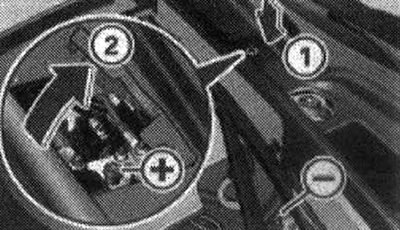
Underhood space: terminals for connecting jumper cables and charger
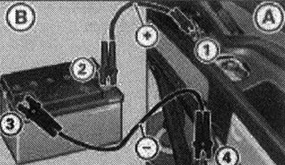
Starting the engine from another car's battery: A - discharged battery, B - current-discharging battery
Both jump starter cables must be connected in the specified sequence! The connections for engine starting assistance are located in the engine compartment.
Connecting the positive terminals with the positive cable (red)
Remove cover "1" by pressing the arrow. Fold back cover "2" of the positive pole. Fasten one end of the cable to the starting auxiliary bolt "1" (bolt under the cover ="positive terminal") of the vehicle "A" to be started. Fasten the other end of the cable to the positive pole "2" of the current-dispensing battery "B".
Connecting the negative terminals with a negative cable (black)
Attach 1 end of the cable to the negative pole "3" of the current-dispensing battery "B". The other end of the cable is connected to the starting auxiliary bolt "4" (hexagonal bolt ="negative terminal") of the vehicle "A" being started.
Starting the engine
Start the engine of the current-dispensing vehicle "B" and let it idle. Start the engine with the discharged battery "A". If the engine does not start: stop trying to start after 10 seconds and repeat the starting process after 30 seconds. When the engine starts, disconnect both cables, acting strictly in the reverse order. Close the cover "2" of the positive terminal and install the cover "1". The battery of the vehicle is equipped with an external ventilation system. The gas formed in the battery is thereby removed from the vehicle. Ensure sufficient metallic contact of the connected terminal clamps.
Caution. Do not touch uninsulated parts of the terminal clamps. In addition, to avoid short circuits, the jump starter cable connected to the positive terminal of the battery must not come into contact with conductive parts of the vehicle. Do not lean over the battery - risk of chemical burns! It is necessary to tighten the battery caps tightly. No ignition sources are allowed near the battery (open light, lit cigarettes, etc.) - explosion hazard. In case of assistance in starting the engine of another vehicle, the jump starter cables must be positioned so that they cannot be touched by the rotating parts of the underhood space of the other vehicle.
Towing and towing
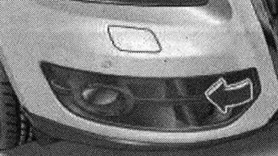
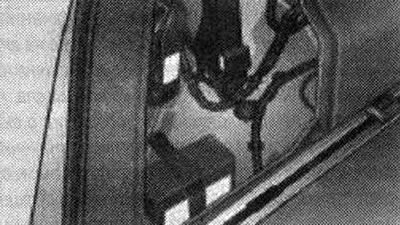
Front right side: removing the lid
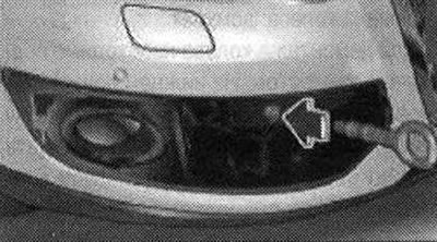
Front right side without cover: screwing in the towing eye
The front towing eye is only installed if necessary. The thread for the towing eye is located under the cover on the right front of the bumper. Remove the towing eye included in the tool kit. Carefully remove the cover in the direction of the arrow. Screw the towing eye into the threaded hole as far as it will go. After use, unscrew the towing eye and put it in the tool kit. The towing eye must always be in the car. When finally installing the cover, make sure that its projections first enter the fasteners next to the radiator grille. Then install the opposite part of the cover and press it into the fasteners. If the towing eye is not screwed in all the way, the threads may strip during towing - risk of accident!
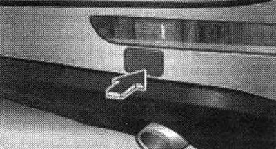
Rear bumper: cap
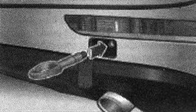
Rear bumper: screwing in the towing eye
On vehicles without a towbar, the factory-fitted towing eye is located on the right rear of the bumper.
Car with towing eye
Remove the towing eye included in the tool kit. To remove the cap from the bumper, sharply and forcefully press the lower edge of the cover inward. Screw the towing eye into the threaded hole until it stops.
Car with towbar
Extend the towbar. Secure the towing rod or towing cable to the towbar. After use, unscrew the towing eye and put it in the tool kit. Install the cover in the bumper. The towing eye must always be in the car. On cars with a factory towbar, there is no threaded hole for the towing eye at the rear. If the towing eye is not screwed in all the way, the threads may strip during towing - risk of accident!
(The original article is located on the online resource: AUDIMANUAL.ru)