
Table of contents: Removal ↓ Installation ↓
Removal
Directions: Mark the position of the front wheels in relation to the hubs with paint. This is necessary to reinstall the wheels in their original position, which maintains their balance. With the car standing on its wheels, loosen the front wheel mounting bolts, then lift the car, unscrew the bolts and remove the front wheels.
To prevent the steering knuckles from sagging after removing the shock absorber strut, support them with a jack through a wooden block. Otherwise, the lower arm joint may be damaged.
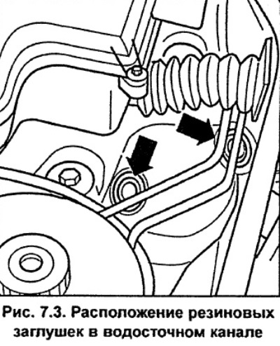
Remove the rubber plugs from the drain channel (see fig. 7.3).
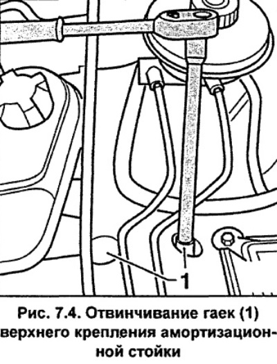
Carefully unscrew the two nuts of the upper shock absorber mount, being careful not to damage the protective coating of the brake pipes (see fig. 7.4).
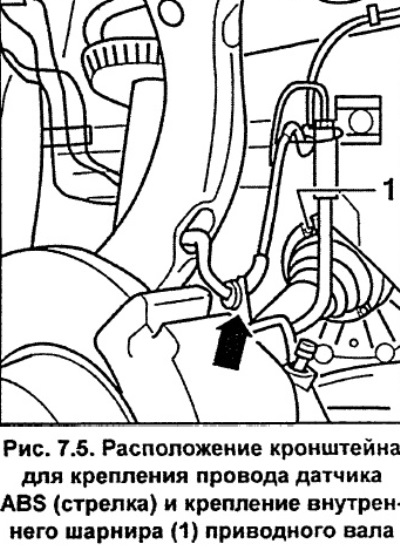
Remove the ABS speed sensor wire from the bracket on the brake caliper (see fig. 7.5).
Unscrew nut 1 (Fig. 7.6), remove the bolt and, pulling upwards, remove the upper transverse arms 2 from the steering knuckle.
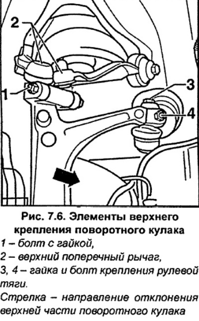
Caution. Do not widen the grooves in the steering knuckle with a screwdriver or other tool. Do not unscrew the bolts securing the steering rod to the steering knuckle, otherwise it will be necessary to adjust the installation angles of the front wheels 3 and 4 (Fig. 7.6).
Tilt the top of the steering knuckle to the side (arrow, Fig. 7.6).
Unscrew the nut securing the ball joint pin of the lower arm to the steering knuckle, while using a 4 mm wrench to hold the ball joint pin from turning.
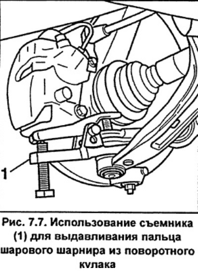
Use a puller to push the ball joint pin out of the steering knuckle (see fig. 7.7).
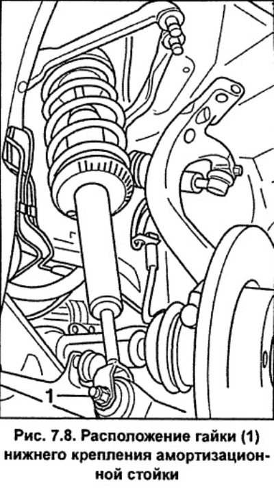
Unscrew the nut and remove the bolt securing the shock absorber strut to the lower wishbone (see fig. 7.8).
Remove the shock absorber strut from under the front fender, being careful not to damage the protective cover of the constant velocity joint of the shaft, drive.
Installation
Install the shock absorber so that the hole in the lower spring seat is directed towards the center of the vehicle (see fig. 7.9).
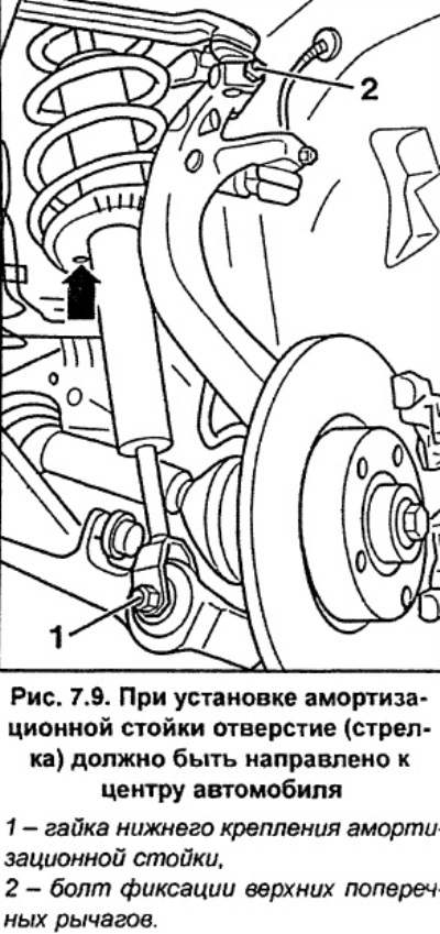
Install the lower shock absorber mount fork onto the wishbone and insert the bolt and screw the nut onto it, but do not tighten it at this stage (see fig. 7.9). The final tightening of the nut must be carried out after the vehicle has been installed on the wheels.
Insert the upper wishbone pivot pins into the steering knuckle as far as they will go and secure them with a bolt and nut, tightening them to a torque of 40 Nm (Fig. 7.9).
Insert the lower arm ball joint pin into the steering knuckle and secure it with a nut, tightening it to a torque of 100 Nm, while using a 4 mm wrench to prevent the ball joint pin from turning.
Secure the ABS sensor wire to the brake caliper bracket.
Install the upper part of the shock absorber strut and secure it with new nuts, tightening them to a torque of 20 Nm, but without damaging the protective coating of the brake pipes.
Install rubber plugs into the gutter.
Apply a thin layer of grease to the flange of the hub that centers the wheel disk. In accordance with the previously applied marks, install the wheel and secure it with bolts. Lower the car and tighten the wheel mounting bolts to a torque of 120 Nm.
Tighten the lower shock absorber strut mounting nut to 90 Nm.
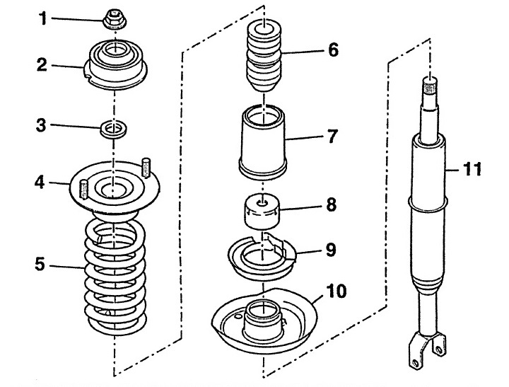
Fig. 7.10. Shock absorber strut elements
1 - self-locking nut with flange, 60 Nm,
A new nut must be used during installation.
2 - shock absorber strut bearing,
3 - washer,
4 - upper spring plate,
5 - cylindrical coil spring,
There should be no damage on the surface of the spring.
6 - stop buffer,
Installed in the upper spring plate,
7 - protective cover,
8 - protective cover,
9 - spring support,
10 - lower spring plate,
11 - shock absorber