Please note. Depending on the engine/gearbox installed in the vehicle, the inner constant velocity joint may be a ball or roller joint (Tripod). The roller joint uses three rollers arranged at an angle of 120° mounted on a three-arm holder instead of six balls. The roller joint is not replaced separately, and if it fails, it must be replaced together with the drive shaft.
Disassembly
Remove the drive shaft from the vehicle.
Secure the drive shaft in a vice with soft jaws.
Remove or cut the clamps holding the protective boot and slide the boot off the hinge and onto the drive shaft.
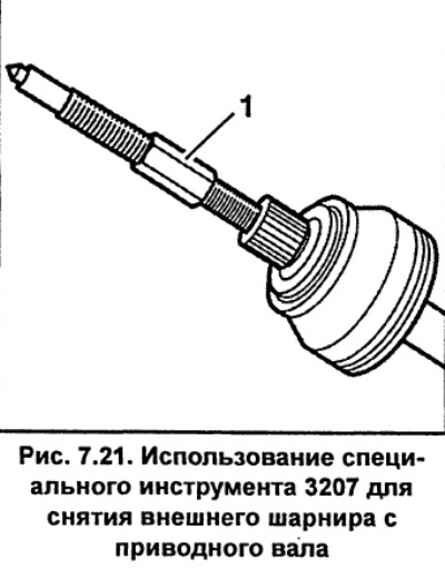
Screw special tool 1 (Fig. 7.21) VAG-3207 with M14 or M16 thread into the joint shaft and screw the tool until the outer joint is removed from the drive shaft.
Internal ball joint
The internal constant velocity joint cannot be repaired and if it fails, it must be replaced completely.
Secure the drive shaft in a vice with soft jaws.
Using special VAG-161a or HAZET 2525K snap ring pliers, remove the snap ring from the end of the inner constant velocity joint.
Using a drift, remove the protective cover of the joint with the flange. The drift must be installed in turn at different points along the perimeter of the flange, for its uniform removal. Move the protective cover to the drive shaft.
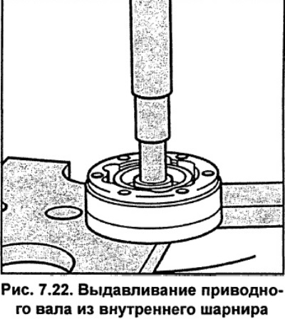
Place the joint under a press and, using a round tool, press the drive shaft out of it, while supporting the inner sleeve of the joint (see fig. 7.22).
Clean the joint from grease.
Assembly
Replace damaged protective covers. To do this, remove the protective cover by sliding it along the drive shaft; to make removing the cover easier, you can apply a thin layer of grease to the drive shaft.
Internal ball joint
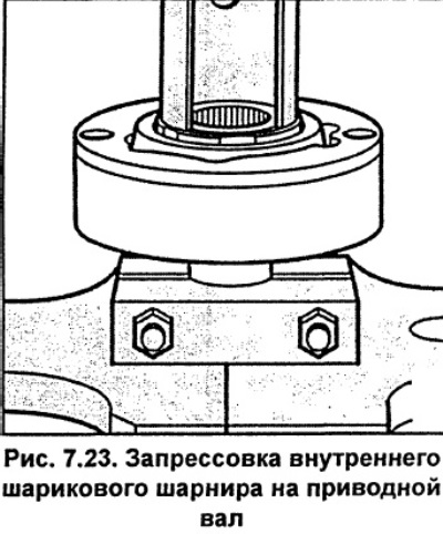
Secure the inner constant velocity joint in a vice with soft jaws and insert the drive shaft into it. If the shaft does not fit into the joint, press the joint onto the shaft using a press, with the shaft resting on the support underneath (see fig. 7.23). Check that the chamfer of the inner sleeve of the joint should be on the drive shaft side
Using special pliers VAG-161a or HAZET 2525K, install a new spring retaining ring into the groove of the drive shaft.
Fill the inner joint and protective boot with grease.
Apply VW sealant D-3 to the end surface of the flange of the protective boot of the hinge and install the protective boot with the flange on the hinge.
Remove the protective film from the new gasket and glue the gasket to the hinge.
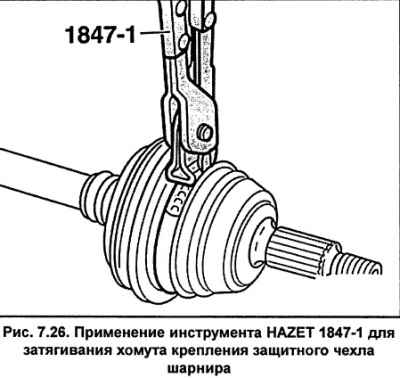
Place a small clamp on the protective cover and secure it with HAZET1847-1 pliers.
Slide the outer constant velocity joint boot onto the drive shaft.
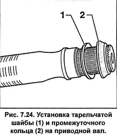
Install a disc washer on the drive shaft, with the convex side facing the joint, and a thrust ring (see fig. 7.24).
Install a new snap ring on the drive shaft, secure the shaft in a vice with soft jaws and use an aluminum or copper hammer to tap the joint onto the drive shaft until the snap ring fits neatly into the groove on the inside of the joint.
Install a protective cover on the hinge. Depending on the model, protective covers can be made of rubber or plastic.
Rubber protective cover
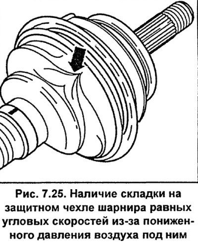
When installing a protective cover on a hinge, as a result of its compression, the air pressure inside the cover is usually lower than atmospheric pressure, resulting in folds appearing on the cover (see fig. 7.25). To equalize the air pressure under the protective cover, use a screwdriver to lift the cover from the drive shaft side.
Secure the protective cover with new clamps. To secure the clamps, use the HAZET 1847-1 tool (see fig. 7.26).