



Caution. Do not lower the vehicle onto its wheels with one or both drive shafts removed, as this will damage the wheel hub bearings. If it is necessary to lower the vehicle onto its wheels and move it with the drive shafts removed, install the outer drive shaft joints instead of the drive shafts and tighten the joint mounting bolts to 50 Nm.
With the vehicle standing on its wheels, loosen the bolts securing the outer joints of the drive shafts to the front wheel hubs.
Mark the position of the front wheels in relation to the hubs with paint. This is necessary for reinstalling the wheels in their original position, as a result of which their balance is maintained. With the car standing on its wheels, loosen the front wheel mounting bolts.
Raise the front of the vehicle and support it on stands.
Unscrew the bolts and remove the front wheels.
Unscrew the bolts securing the outer joints of the drive shafts to the front wheel hubs.
Unscrew bolts 1 (Fig. 7.5) securing the inner joints of the drive shafts to the gearbox drive flanges.
Remove the ABS speed sensor wire from the bracket on the brake caliper (see fig. 7.5).
Unscrew nut 1 (Fig. 7.6), remove the bolt and, pulling upwards, remove the upper transverse arms 2 from the steering knuckle.
Caution. Do not widen the grooves in the steering knuckle with a screwdriver or other tool. Do not unscrew the bolts securing the steering rod to the steering knuckle, otherwise it will be necessary to adjust the installation angles of the front wheels 3 and 4 (Fig. 7.6).
Tilt the top of the steering knuckle to the side (arrow, Fig. 7.6).
Remove the drive shaft from the vehicle.
Installation
Install the drive shaft onto the vehicle.
Screw in the drive shaft mounting bolts to the gearbox flange and, diagonally, tighten the M8 bolts to 40 Nm and the M10 bolts to 80 Nm.
Screw in and tighten to the required torque the bolts securing the constant velocity joint of the drive shaft to the gearbox flange.
Tightening torques:
- m8 bolts - 40 Nm;
- m10 bolts - 50 Nm.
Thread the new drive shaft to hub bolt into place, tightening it securely at this point.
Install the upper wishbones all the way into the steering knuckle and secure them with a bolt and nut, tightening them to a torque of 40 Nm (Fig. 7.6).
Secure the ABS sensor wire to the brake caliper bracket.
Apply a thin layer of grease to the flange of the hub that centers the wheel disk. In accordance with the previously applied marks, install the wheel and secure it with bolts. Lower the car and tighten the wheel mounting bolts to a torque of 120 Nm.
Finally tighten the new drive shaft to hub bolt.
Tightening torques:
- bolts M14-115N-M + tighten by 180°;
- m16 bolts - 190 Nm + turn 180°.
Caution: Tighten the drive shaft mounting bolt only with the vehicle standing on its wheels.
Amount of grease to fill the outer joint of the drive shaft
Please note: Different grades of grease must be used for joints of different diameters.
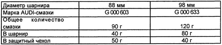
Quantity of AUDI grease G 000 603 for filling the joints of the drive shaft
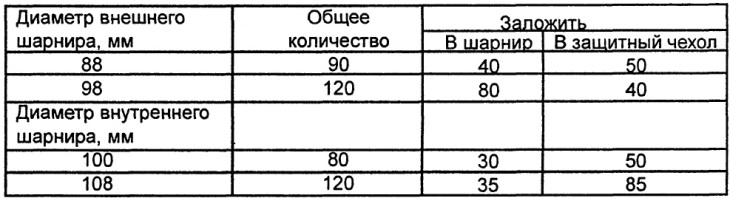
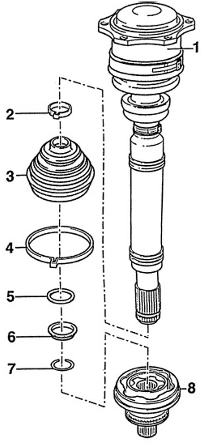
Fig. 7.19. Drive shaft with tripod joint
1 - drive shaft with internal Tripod joint,
2 - clamp,
A new clamp must be used during installation.
3 - protective cover,
It is necessary to check for cracks, abrasions and tears.
4 - clamp,
A new clamp must be used during installation.
5 - washer,
The concave side of the washer should be adjacent to the thrust ring.
6 - plastic ring,
The side with the smaller diameter should face outward.
7 - retaining ring,
A new snap ring must be used during installation. Before installing the joint, the snap ring is installed in the groove of the drive shaft.
8 - external constant velocity joint
If the unit is damaged, it is replaced entirely. Depending on the engine/gearbox, joints with a diameter of 88 or 98 mm are used. When installing on the drive shaft, hammer the joint with a plastic hammer until it is secured with a locking ring.
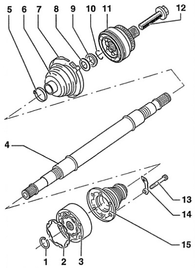
Fig. 7.20. Drive shaft with ball joint.
1 - retaining ring,
The retaining ring is removed using round-nose pliers.
2 - gasket,
When installing, you must use a new gasket. Remove the protective film from the gasket and glue the gasket to the hinge.
3 - internal constant velocity joint,
Depending on the engine/gearbox, joints with a diameter of 100 or 1088 mm are used.
4 - drive shaft,
5 - clamp,
A new clamp must be used during installation.
6 - protective cover,
It is necessary to check for cracks, abrasions and tears. Before installing the smaller clamp of the protective cover, release air from under the protective cover.
7 - clamp,
A new clamp must be used during installation.
8 - washer,
When installing, the concave side of the washer must be in contact with the thrust ring.
9 - thrust ring,
10- retaining ring,
A new snap ring must be used during installation. Before installing the joint, the snap ring must be installed in the groove of the drive shaft.
11 - external constant velocity joint,
Depending on the engine/gearbox, joints with a diameter of 88 or 98 mm are used. The joint is replaced as an assembly. When installing on the drive shaft, tap the joint with a plastic hammer until it is secured with a locking ring.
12 - bolt,
When installing, a new bolt must be used. When tightening the bolt, the vehicle must be standing on its wheels.
Tightening torques:
- Bolt M14 - 115Nm + turn by 180°;
- Bolt M16 - 190 Nm + tighten by 180°.
13 - bolt,
Tightening torques:
- Bolt M8 - 40 Nm;
- Bolt M10 - 80 Nm.
14 - plate,
15 - protective cover of the hinge with flange,
There is a hole for air release. It is necessary to check for cracks, abrasions and tears. Before assembling the hinge, apply a thin layer of AUDl-sealant D3 to the flange.
[The original publication in its entirety is posted on the website AUDIMANUAL.ru]