Repair Chevrolet Repair Toyota Repair Honda Repair AvtoVAZ Repair Mercedes-Benz Repair BMW Repair Opel
Home  |  Contacts  |  Sitemap  |    
English Русский
Български
Беларускі
Український
Српски
Hrvatski
Română
Polski
Slovenský
Magyar
AudiManual.ru


  • AUDI 80
  • AUDI 100
  • AUDI A3
  • AUDI A4
  • AUDI A6
  • AUDI A8
  • AUDI Q
  • OTHER
  • ARTICLES
B8 (2007-2015) B7 (2004-2008) B6 (2000-2006) B6 (2000-2006, petrol) B5 (1994-2001) B5 (1994-2001, petrol)

Removal and installation the front shock absorber / disassembling the shock absorber strut (Audi A4 B6)

  • Home
  • Audi A4
  • B6 (2000-2006)
  • Chassis
  • Car suspension
  • Removal and installation the front shock absorber / disassembling the shock absorber strut
            0
Table of contents: Removal ↓ Installation ↓
Removal and installation the front shock absorber / disassembling the shock absorber strut

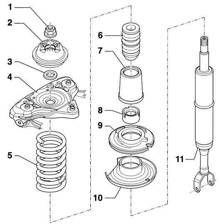
  • 1 - Flange nut, 50Nm, self-locking, be sure to replace
  • 2 — Shock absorber support
  • 3 — Washer
  • 4 - Support
  • 5 - Coil spring
  • 6 - Additional spring
  • 7 - Protective cover
  • 8 — Protective cap
  • 9 — Lower spring support
  • 10 — Lower spring plate
  • 11 — Shock absorber


Removal


1. Remove the shock absorber strut.

2. The shock absorber strut can only be disassembled using a special tool.

Warning: The shock absorber spring is compressed with great force. To remove the shock absorber, it is necessary to compress the spring with a special tool.


Warning: Never remove the shock absorber unless the spring is securely compressed. When installing the spring compressor, make sure that the spring coils are securely gripped and that the compressor cannot slip off. The spring is compressed with great force. Use only a reliable tool. Never tie the spring with wire. Risk of accident!


3. Clamp the spring with the tip in a vice.

3. Clamp the spring with the tip in a vice.


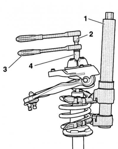
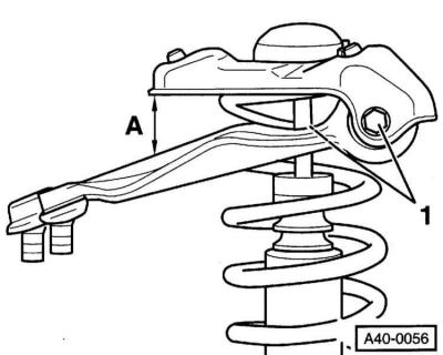
5. Compress the spring with a suitable tool. AUDI service stations use the VAG 1752/1 (1) tool for this purpose.


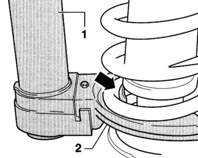
6. When compressing, ensure that the spring is correctly positioned in the device (arrow on the accompanying illustration). (1) – compression device, (2) – support for spring coils.

6. When compressing, ensure that the spring is correctly positioned in the device (arrow on the…


7. Compress the spring so that the top plate is released.

8. Unscrew the flange nut securing the stem. While doing this, hold the stem from turning with an Allen key. This requires a special tool (2, 3 and 4) as shown in Figure 4.3 (HAZET 4910/13 or AUDI-T10001/7, T10001/11 and T10001/3).

9. Remove the compressed spring together with the compressor tool.

10. Remove the protective cover (1) and the lower spring support (2).

10. Remove the protective cover (1) and the lower spring support (2).


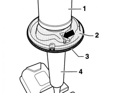
11. Mark the position of the lower plate in relation to the shock absorber (4).

12. Loosen the plate (3) using a plastic hammer and lift it upward.


Installation


Warning: There are springs of different tolerance groups. Only springs with the same color mark should be used. It is recommended to replace springs and shock absorbers in pairs, i.e. on both sides of the car.


1. Clamp the new shock absorber cartridge with the tip in the shock absorber strut mounts or in a vice with pads.

2. Transfer the mark from the old one to the new shock absorber. Carefully install the lower spring plate with a plastic hammer until it stops on the shock absorber. Make sure that the mark on the plate matches the mark on the shock absorber.
  • A — Shock absorber/control arm axis
  • I — Left shock absorber strut, B = 65±2°
  • II — Right shock absorber strut, C = 87±2°

II — Right shock absorber strut, C = 87±2°


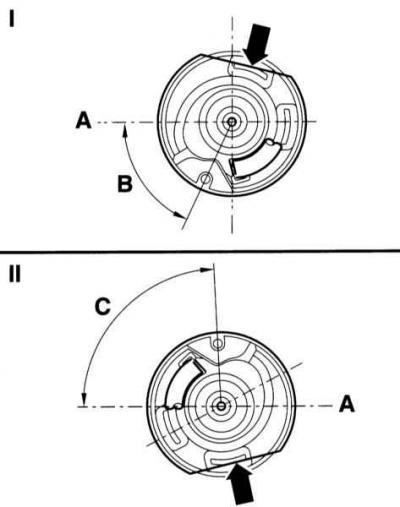
3. The position of the lower plate is determined by the dimensions shown in the illustration.

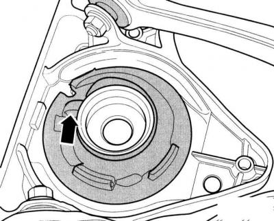
4. The cut of the plate (arrow) must provide access to the body.

5. Reinstall the lower spring support and protective cover.

5. Reinstall the lower spring support and protective cover.


6. Install the compressed spring together with the compression device. The end of the spring coil should be adjacent to the stop.


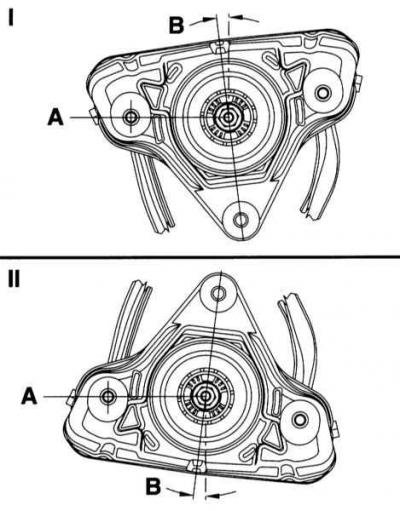
7. Install the shock absorber support with the upper spring support on the compressed spring so that the spring support is adjacent to the end of the spring coil (arrow on the accompanying illustration). A deviation of ±2° is allowed.

7. Install the shock absorber support with the upper spring support on the compressed spring so…


8. Install the washer and shock absorber support.

Caution: Make sure the end of the spring is in contact with the stop of the upper spring support.


9. Tighten the new flange nut with the special tool to the torque 50Nm. Do not release the spring yet.

10. Press the shock absorber strut vertically using the VAG 1752/2 compression tool.

11. Release the lower locking lever and rotate the upper spring plate until the shock absorber support scale is at the 7° mark.

11. Release the lower locking lever and rotate the upper spring plate until the shock absorber…


12. Make sure that the ends of the spring are in contact with the stops of the upper and lower spring supports.


  • I — Left in the direction of travel
  • II - On the right in the direction of travel
  • A - Shock absorber/control arm axis
  • B — Installation angle

B — Installation angle


13. Lock the locking lever.

14. The spring support lever of the VAG 1752/2 tool (arrow) must coincide with the center of the support.

15. Carefully loosen the spring compressor and remove it.

16. Check the adjustment. If necessary, repeat the procedure.

17. Reinstall the shock absorber strut, refer to the relevant section.

(This article was copied from an online resource: «AudiManual.ru»)
The article was checked by auto expert Elisey Ermolaev
This article is available at russian, bulgarian, belarusian, ukrainian, serbian, croatian, romanian, polish, slovak, hungarian

Share information:
Previous articles
Audi A4 B6: Car suspension
Next articles

Removal and installation the front shock absorber strut
Front wheel suspension
Safety measures during work
Suspension and steering specifications
Rear wheel suspension
Removal and installation the rear coil spring
Removal and installation the rear shock absorber
Wheel alignment angles of a car


Similar articles on other Audi car models:
Removal and installation the shock absorber/disassembling the… Audi 80 B3 (1986-1991)
Rear suspension strut/shock absorber — removal and installation Audi 100 C3 (1982-1990, diesel)
Removal and installation the shock absorber strut and wheel… Audi A3 Type 8L (1996-2003)
Shock absorber strut with air spring — removal and installation Audi A6 C5 Allroad (1999-2005)
Shock absorber strut Audi A8 D2 (1994-2002)
Spring strut with upper support, shock absorber fork, upper… Audi Q5 Type 8R (2008-2017)
Removal and installation the front door opening limiter Audi A2 (1999-2005)
Link to this page in different formats


Visitor comments

No comments yet


How much will 26 + 15 =


A4(B8, 2007-2015) 
  • General information
  • Operating instructions
  • Power unit
  • Petrol engines 1.8 l
  • Petrol engines 1.8/2.0 l
  • Petrol engines 3.0 l
  • Petrol engines 3.2 l
  • Fuel system (petrol)
  • Diesel engines 2.0 l (CA*)
  • Diesel engines 2.0 l (CJCB)
  • Diesel engines 2.7/3.0 l
  • Diesel engines 3.0 l
  • Fuel system (diesel)
  • Transmission
  • Manual gearbox 0B1
  • Manual gearbox 0B2
  • Manual gearbox 0B3
  • Manual gearbox 0B4
  • Automatic transmission 0B5
  • Automatic transmission 0B6
  • Automatic transmission 0AW
  • All-wheel drive system
  • Chassis
  • Front suspension
  • Rear suspension
  • Brake system
  • Steering system
  • Body
  • Exterior
  • Interior
  • Seats
  • Doors, locks and windows
  • Security system
  • Heating and air conditioning
  • Electrical equipment
  • Audio system
  • Power devices
  • Equipment and devices
  • Lighting and lamps
  • Electrical circuits
 
A4(B7, 2004-2008) 
  • General information
  • Introduction to manual
  • Troubleshooting
  • Operating instructions
  • Maintenance
  • Power unit
  • Petrol engines 2.0 (ALT)
  • Petrol engines 2.0 (TFSI)
  • Petrol engines 1.8 (MPI)
  • Diesel engines
  • Cooling system
  • Air conditioner
  • Fuel and exhaust system
  • Ignition system
  • Starting and charging
  • Transmission
  • Clutch
  • Manual gearbox
  • Automatic gearbox
  • Drive shafts
  • Chassis
  • Brake system
  • Front suspension
  • Rear suspension
  • Steering
  • Body
  • Exterior
  • Interior
  • Electrical equipment
  • Equipment and devices
  • Lighting and signaling
  • Windscreen wipers and washers
  • Electrical diagrams
  • Electrical diagrams (since 2007)
 
A4(B6, 2000-2006) 
  • General information
  • Vehicle Description
  • User manual
  • Maintenance
  • Power unit
  • Gasoline engine
  • Diesel engine
  • Lubrication system
  • Cooling system
  • Supply system
  • Injection system
  • Exhaust system
  • Ignition and control
  • Transmission
  • Gear box
  • Clutch and drive shafts
  • Chassis
  • Brake system
  • Car suspension
  • Steering
  • Body
  • Heating and ventilation
  • Exterior (external elements)
  • Interior (internal elements)
  • Electrical equipment
  • Power devices
  • Lighting and appliances
  • Electrical circuits
 
A4(B6, 2000-2006, petrol) 
  • General information
  • Introduction to the guide
  • Car care
  • Power unit
  • Engine repair
  • Lubrication system
  • Cooling system
  • Injection and control system
  • Ignition system
  • Power and exhaust system
  • Transmission
  • Clutch and drive shafts
  • Car gearbox
  • Chassis
  • Suspension and wheels
  • Steering
  • Brake system
  • Body
  • Interior
  • Exterior
  • Electrical equipment
  • Equipment and devices
  • Lighting and signaling
  • Power devices
  • Electrical circuits
 
A4(B5, 1994-2001) 
  • General information
  • Introduction to the guide
  • Car care
  • Maintenance (gasoline)
  • Maintenance (diesel)
  • Power unit
  • Gasoline engines
  • Diesel engines
  • Engine overhaul
  • Cooling system
  • Fuel injection (gasoline)
  • Fuel system (diesel)
  • Exhaust system
  • Ignition system
  • Transmission
  • Clutch
  • Mechanical gearbox
  • Automatic gearbox
  • Drive shafts
  • Chassis
  • Brake system
  • Car suspension
  • Steering
  • Body
  • Exterior
  • Interior
  • Doors, locks and windows
  • Heating and ventilation
  • Electrical equipment
  • Power devices
  • Equipment and devices
  • Electrical circuits
 
A4(B5, 1994-2001, petrol) 
  • General information
  • Vehicle description
  • Maintenance
  • Power unit
  • Engine repair
  • Turbocharging
  • Exhaust system
  • Cooling system
  • Ignition system
  • Fuel system
  • Motronic injection system
  • MPI and MPFI injection system
  • Transmission
  • Clutch
  • Gearbox and shafts
  • Chassis
  • Steering
  • Car suspension
  • Brake system
  • Wheels and tires
  • Body
  • Heating and ventilation
  • Body parts
  • Electrical equipment
  • Fuses and relays
  • Power devices
  • Lighting and lamps
  • Tools and devices
  • Electrical circuits
 
AudiManual.ru © 2017-2026 · Mobile version · Feedback · Sitemap: EN BG BY UA RS HR RO PL SK HU · Site search · News and articles
80 B2 · 80 B3 petrol · 80 B3 · 80 B4 · 100 C3 diesel · 100 C3 petrol · 100 C3 · 100 C4 petrol · 100 C4 · A3 Type 8L · A4 B5 petrol · A4 B5 · A4 B6 petrol · A4 B6 · A4 B7 · A4 B8 · A6 C4 · A6 C5 · A6 C5 Allroad · A8 D2 · Q5 Type 8R · Q7 Typ 4L · Audi A2 ·
This site uses cookies 🍪. Click the button to accept this fact.