
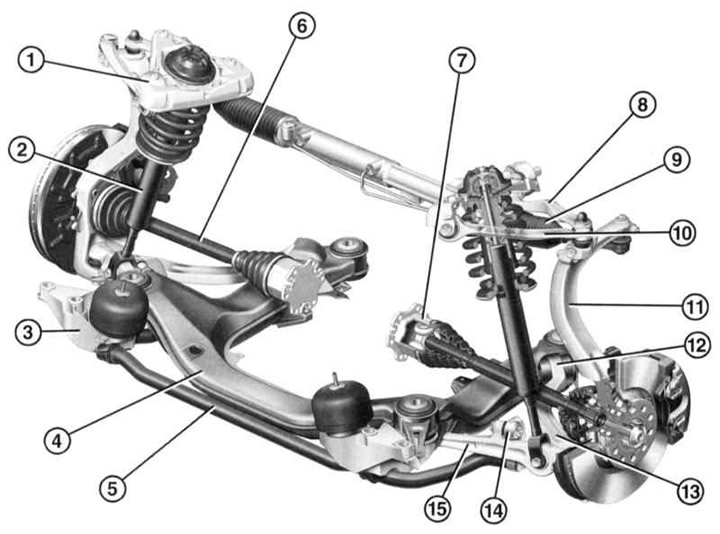
- 1 - Support
- 2 — Shock absorber strut
- 3 - Console
- 4 — Powertrain beam
- 5 — Anti-roll bar
- 6 — Drive shaft
- 7 - "Tripod" hinge
- 8 — Rear lever
- 9 — Steering rod
- 10 — Front arm
- 11 — Pivot support
- 12 — Hydro support
- 13 — Guide lever
- 14 — Connecting rod
- 15 — Carrying lever
Front suspension elements
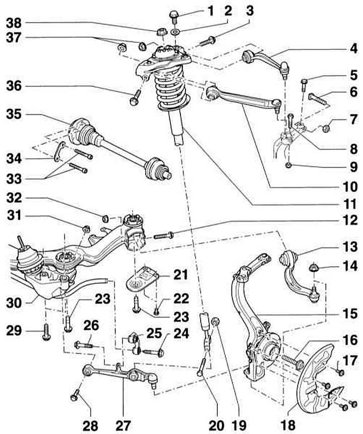
- 1 - Bolt, 75Nm
- 2 — Washer
- 3 - Bolt. Be sure to replace
- 4 — Upper rear suspension arm. Replace the support
- 5 - Bolt, 7Nm
- 6 - Bolt
- 7 — Self-locking nut, 50Nm, be sure to replace
- 8 - Bolt
- 9 — Self-locking nut, 40Nm, be sure to replace
- 10 — Upper front suspension arm. Can only be removed together with the support
- 11 — Shock absorber strut
- 12 - Bolt. Be sure to replace
- 13 — Guide lever with hydraulic support. If significant oil leaks appear on the hydraulic support, the support must be replaced
- 14 - Nut, 120Nm, self-locking. Be sure to replace
- 15 — Wheel bearing housing
- 16 — Flange bolt, be sure to replace. Tightening torque:
- bolt M14: 115Nm and then turn 180°;
- bolt M16: 190Nm and then turn 180°;
- 17 - Bolt, 10Nm
- 18 — Lid
- 19 — Nut, 90Nm, self-locking. Be sure to replace
- 20 - Bolt
- 21 — Powertrain beam support
- 22 - Bolt, 55Nm
- 23 - Bolt, 110Nm and then turn it 90°. Be sure to replace it
- 24 - Bolt, 40Nm and then turn it 90°. Be sure to replace it
- 25 — Connecting rod
- 26 - Bolt, 40Nm and then turn it 90°. Be sure to replace it
- 27 — Lower support arm
- 28 - Bolt. Be sure to replace
- 29 - Bolt, 75Nm. Be sure to replace
- 30 — Powertrain beam. Attention: Do not lift the vehicle by the powertrain beam
- 31 - Nut, 70Nm and then turn it 180°. Be sure to replace it
- 32 - Nut, 70Nm and then turn it 180°. Be sure to replace it
- 33 — Socket head cap screw. Pre-tighten to 15Nm, then to the following torque:
- screw M8 = 40Nm
- screw M10 = 70Nm
- 34 — Backing plate
- 35 — Drive shaft
- 36 - Bolt. Be sure to replace
- 37 - Nut, 50Nm and then tighten 90°. Be sure to replace
- 38 - Flange nut, 50Nm. Be sure to replace
The four-link, independent front suspension has McPherson shock absorbers and a torsion bar.
The shock absorbers consist of cylindrical coil springs, double-pipe shock absorbers and large upper supports. The stabilizer does not participate in the direction of the wheels, but is connected to the shock absorbers via connecting rods.
The shock absorber strut is bolted to the upper arm support and to the front transverse arm.
Optimum driving characteristics and minimal tire wear are only achieved when the wheels are correctly positioned. If the tires are not properly worn or if there is insufficient road holding, optical measurements must be taken and, if necessary, the wheel alignment must be adjusted.
The transmission of torque from the power unit to the wheels is carried out through two drive shafts, each of which, through two constant velocity joints, is connected to the wheels and the main transmission.
The original text is available on the website: AUDImanual.ru