
The load-bearing element of the front suspension is the lower cross beam. The power unit is attached to the beam through the corresponding supports.
The front suspension is independent McPherson type. The upper aluminum alloy arms are connected to the body via rubber bushings, and to the steering knuckle via ball joints. The lower (holding and controlling) the levers are connected to the lower frame via rubber bushings and to the steering knuckle via ball joints.
The elastic element of the front suspension is made in the form of a rack with elastic additional polyurethane elements and suspension travel limiters with a progressive characteristic. The upper part of the shock absorber rack is attached to the upper bracket of the front suspension, and the lower part is attached to the transverse arm.
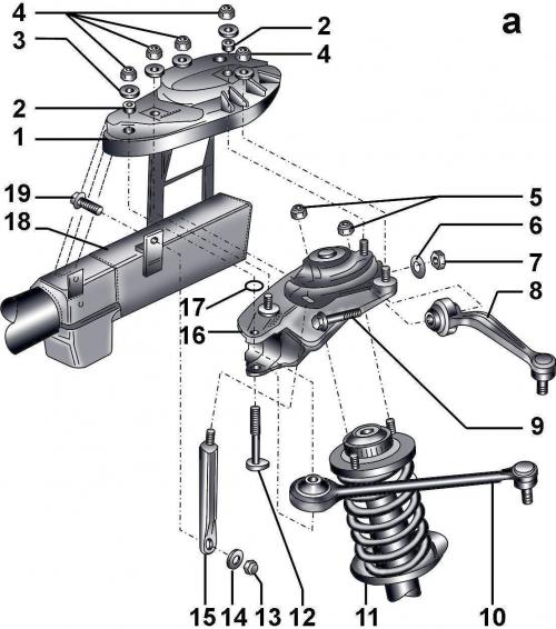
Fig. 12–3a. Elements of the front suspension design: 1 – bracket; 2 – guide bushing; 3 – washer; 4 – self-locking nuts, 100 Nm; 5 – self-locking nuts, 20 Nm; 6 – washer; 7 – self-locking nut, 50 Nm + turn further by 90°; 8 – Upper rear arm; 9 – bolt; 10 - Upper front arm; 11 – shock absorber strut; 12 – bolt; 13 – self-locking nut, 100 Nm; 14 - washer; 15 – support stand, not installed on vehicles with chassis numbers from 4DZ TN 006 420 to 4DZ XN 5 000; 16 – suspension support; 17 – retaining ring; 18 – front longitudinal beam; 19 – bolt; 20 – bolt; 21 – combination bolt, 7 Nm; 22 – square head bolt; 23 - self-locking nut, 50 Nm; 24 – steering rod end; 25 – steering knuckle; 26 – flange bolt, 190 Nm + turn further by 180°; 27 – bolt, 10 Nm; 28 – mudguard; 29 - clamping sleeve; 30 – ABS sensor; 31 – front wheel drive shaft; 32 – bolt, 70 Nm; 33 – self-locking nut, 40 Nm; 34 – lower front frame; 35 – self-locking nuts; 36 – combination bolt, 90 Nm + turn further by 90°; 37 – retaining lever; 38 – lower frame mounting plate; 39 – washer; 40-bolt, 25 Nm; 41 – bolt, 150 Nm + turn further at an angle of 90°; 42 – bolt; 43 – washer; 44, 45 – flange nuts, 100 Nm (for aluminum steering knuckle 125 Nm); 46 – self-locking nut, 90 Nm; 47 – stabilizer earring; 48 – control lever; 49 – clamp; 50 – self-locking nut, 40 Nm + turn further by 90°; 51 – bolt, 150 Nm + turn further by 90°; 52 – lock washer; 53 – washer; 54 – combination bolt, 90 Nm + turn further by 90°; 55 – anti-roll bar; 56 – self-locking nut
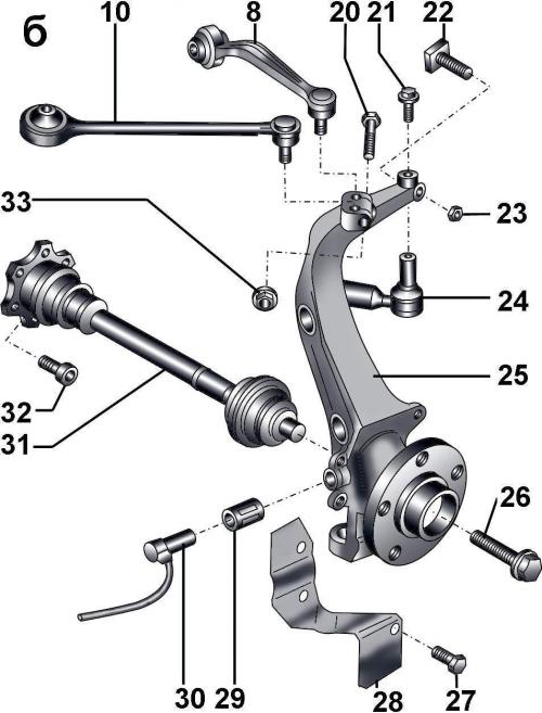
Fig. 12–3b. Elements of the front suspension design: 1 – bracket; 2 – guide bushing; 3 – washer; 4 – self-locking nuts, 100 Nm; 5 – self-locking nuts, 20 Nm; 6 – washer; 7 – self-locking nut, 50 Nm + turn further by 90°; 8 – Upper rear arm; 9 – bolt; 10 - Upper front arm; 11 – shock absorber strut; 12 – bolt; 13 – self-locking nut, 100 Nm; 14 - washer; 15 – support stand, not installed on vehicles with chassis numbers from 4DZ TN 006 420 to 4DZ XN 5 000; 16 – suspension support; 17 – retaining ring; 18 – front longitudinal beam; 19 – bolt; 20 – bolt; 21 – combination bolt, 7 Nm; 22 – square head bolt; 23 - self-locking nut, 50 Nm; 24 – steering rod end; 25 – steering knuckle; 26 – flange bolt, 190 Nm + turn further by 180°; 27 – bolt, 10 Nm; 28 – mudguard; 29 - clamping sleeve; 30 – ABS sensor; 31 – front wheel drive shaft; 32 – bolt, 70 Nm; 33 – self-locking nut, 40 Nm; 34 – lower front frame; 35 – self-locking nuts; 36 – combination bolt, 90 Nm + turn further by 90°; 37 – retaining lever; 38 – lower frame mounting plate; 39 – washer; 40-bolt, 25 Nm; 41 – bolt, 150 Nm + turn further at an angle of 90°; 42 – bolt; 43 – washer; 44, 45 – flange nuts, 100 Nm (for aluminum steering knuckle 125 Nm); 46 – self-locking nut, 90 Nm; 47 – stabilizer earring; 48 – control lever; 49 – clamp; 50 – self-locking nut, 40 Nm + turn further by 90°; 51 – bolt, 150 Nm + turn further by 90°; 52 – lock washer; 53 – washer; 54 – combination bolt, 90 Nm + turn further by 90°; 55 – anti-roll bar; 56 – self-locking nut
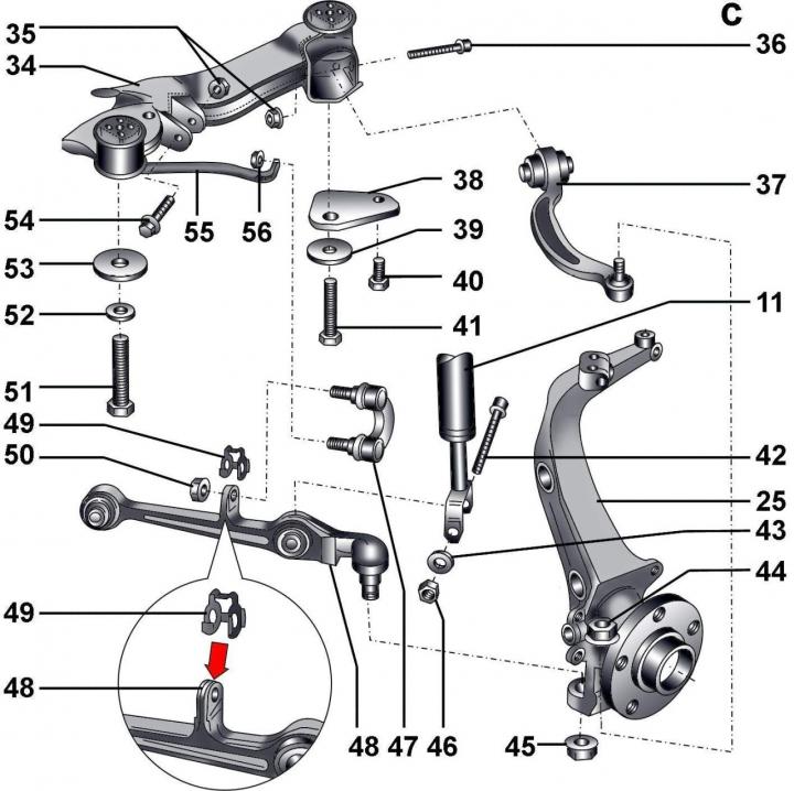
Fig. 12–3c. Elements of the front suspension design: 1 – bracket; 2 – guide bushing; 3 – washer; 4 – self-locking nuts, 100 Nm; 5 – self-locking nuts, 20 Nm; 6 – washer; 7 – self-locking nut, 50 Nm + turn further by 90°; 8 – Upper rear arm; 9 – bolt; 10 - Upper front arm; 11 – shock absorber strut; 12 – bolt; 13 – self-locking nut, 100 Nm; 14 - washer; 15 – support stand, not installed on vehicles with chassis numbers from 4DZ TN 006 420 to 4DZ XN 5 000; 16 – suspension support; 17 – retaining ring; 18 – front longitudinal beam; 19 – bolt; 20 – bolt; 21 – combination bolt, 7 Nm; 22 – square head bolt; 23 - self-locking nut, 50 Nm; 24 – steering rod end; 25 – steering knuckle; 26 – flange bolt, 190 Nm + turn further by 180°; 27 – bolt, 10 Nm; 28 – mudguard; 29 - clamping sleeve; 30 – ABS sensor; 31 – front wheel drive shaft; 32 – bolt, 70 Nm; 33 – self-locking nut, 40 Nm;34 – lower front frame; 35 – self-locking nuts; 36 – combination bolt, 90 Nm + turn further by 90°; 37 – retaining lever; 38 – lower frame mounting plate; 39 – washer; 40-bolt, 25 Nm; 41 – bolt, 150 Nm + turn further at an angle of 90°; 42 – bolt; 43 – washer; 44, 45 – flange nuts, 100 Nm (for aluminum steering knuckle 125 Nm); 46 – self-locking nut, 90 Nm; 47 – stabilizer earring; 48 – control lever; 49 – clamp; 50 – self-locking nut, 40 Nm + turn further by 90°; 51 – bolt, 150 Nm + turn further by 90°; 52 – lock washer; 53 – washer; 54 – combination bolt, 90 Nm + turn further by 90°; 55 – anti-roll bar; 56 – self-locking nut
Fig. 12-3a, 12-3b, 12-3c show the elements of the front suspension design.
Warnings: It is strictly forbidden to carry out welding and straightening work on the front suspension elements. Be sure to replace self-locking nuts, as well as bolts with traces of corrosion.
Do not lift the vehicle by the lower front frame.
Tightening torques, Nm
| Front suspension | |
| Shock absorber to lower wishbone | 90 |
| Shock absorber to upper bracket | 20 |
| Upper arm joint nuts to steering knuckle | 40 |
| Lower wishbone to steering knuckle | 100 |
| Lower trailing arm to steering knuckle | 100 |
| Brake shield to steering knuckle | 10 |
| Brake caliper to steering knuckle | 190 |
| Lower frame mounting bolts | 150 + turn to 90° angle |
| Lower arm to lower frame mounting bolts | 90 + turn by 90° |
| Lower frame support plate mounting bolts | 25 |
| Earring to the anti-roll bar | 90 |
| Earring to wishbone | 70 |
| Stabilizer Bracket Mounting Bolts | 20 |
| Rear suspension | |
| Upper shock absorber mounting nuts to the body | 25 |
| Lower shock absorber mounting bolt to wishbone | 65 |
| Fuel tank mounting nut | 25 |
| Wishbone mounting nut | 80 + turn to 90° angle |
| Eccentric bolt for mounting the transverse arm | 95 |
| Lower rear frame mounting bolts | 150 + turn to 90° angle |
[The original text of the material can be found on the website «audimanual.ru»]