
Note: On models with separate stand and wheel bearing housing (chassis number F89J3 73 73599 - approximately since April 1988) the strut can be removed leaving the wheel bearing housing and associated parts in place by following steps 3, 4, 5, 8, 10, 18, 15, 16 and 17, in that order.
1. Apply the handbrake, remove the trim from the corresponding front wheel.
2. Loosen the drive shaft nut or bolt.
3. Loosen the wheel bolts.
4. Jack up the front of the car and support it on axle stands.
5. Remove the wheel.
6. Remove the drive shaft nut and washer or bolt.
7. Remove the brake disc as described in Section 9.
8. Unscrew the hydraulic brake hose hanger from the strut.
9. Loosen and remove the tie bolt securing the lower suspension ball joint to the wheel bearing housing.
10. Disconnect the steering rod from the rack as described in Chapter 14.
11. On models with power steering, remove the nut securing the stabilizer bar link to the lower control arm, remove the washer and rubber.
12. Move the lower suspension arm down, disconnect the ball joint from the strut.
13. On direct-acting steering models, remove the stabilizer bar completely as described in Chapter 6.
14. Using an extractor, push the drive shaft through the hub and secure it to the axle support.
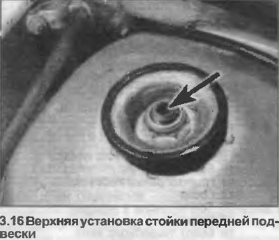
15. From the engine bay, remove the plastic covering from the top of the strut.
16. Support the base of the strut, then remove the nut from the top of the piston rod (photo).
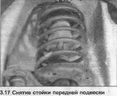
17. Lower the front suspension strut and remove it from under the wing (photo).
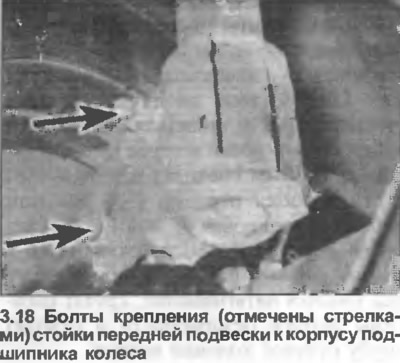
18. If removing the strut on April 1988 models, note the position of the wheel bearing housing relative to the strut, remove the two bolts and separate the housing. Note that the bolt heads face forward (photo).
19. Installation is carried out in the reverse order. Tighten all nuts and bolts with the tightening force specified in the Specification. Follow Section 8 when installing the drive shaft, Section 9 when installing the brake disc, and Chapter 6 from this Section when installing the anti-roll bar.