
Table of contents: Removal ↓ Installation ↓
Removal
1. Remove the decorative cap, loosen the mounting bolts of the corresponding wheel while the car is standing on its wheels.
2. Place chocks under the rear wheels, apply the handbrake, raise the front of the car and install safety stands. Remove the corresponding front wheel.
3. On models equipped with xenon headlights, release the clamp and disconnect the vehicle level sensor control rod from the lower front control arm as described in chapter 12.
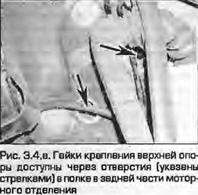
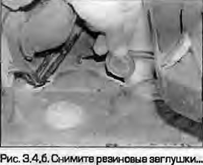
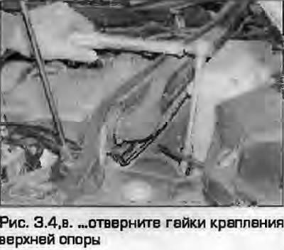
4. The upper strut mounting nuts are accessible through two holes in the butt at the rear of the engine compartment. The holes are closed with plugs. Support the strut with a trolley jack, remove the plugs, unscrew the upper strut mounting nuts using a head with an extension and a ratchet (fig. 3.4, a-c).
 |
 |
5. Remove the ABS wheel sensor as described in paragraph 19 of Chapter 9 and move it away from the suspension strut.
6. Loosen the fastening nut, remove the clamping bolt on top of the steering knuckle, as described in paragraph 5. Separate the front and rear arm joints from the steering knuckle. Do not use screwdrivers or chisels to separate the clamp. Try not to damage the rubber boots of the joints.
7. Loosen the mounting nuts and separate the lower rear wishbone from the base of the steering knuckle using a ball joint puller. Be careful not to damage the rubber boot (see paragraph 5)! This will allow you to remove the lower strut mounting bolt from the front lower control arm.
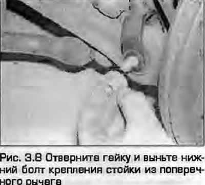
8. Unscrew the nut and remove the lower suspension strut mounting bolt from the wishbone (Fig. 3.8).
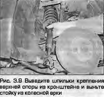
9. Remove the upper support mounting pins from the bracket and remove the strut from under the wheel arch (Fig. 3.9).
Installation
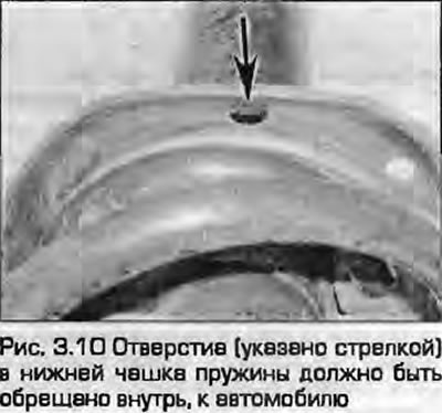
10. Place the strut in the installation location and insert the upper support mounting pins into the bracket. Make sure that the hole in the lower support of the strut spring faces inward, towards the vehicle (Fig. 3.10).
11. Secure the bracket to the lower wishbone with a bolt, screw in a new mounting nut and tighten it at this stage by hand.
12. Attach the lower wishbone to the steering knuckle base - see paragraph 5. Install a new self-locking nut and tighten it to the specified torque.
13. Attach the upper wishbones to the top of the steering knuckle - see paragraph 5. Install the clamp tie bolt with a new self-locking nut, tighten to the specified torque. Press down both arms while tightening the nut so that both support pins are properly locked.
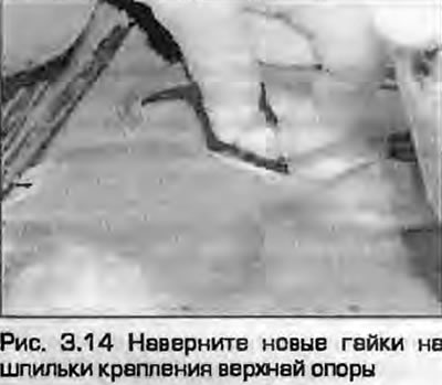
14. Screw new nuts onto the studs of the upper support of the rack and tighten them to the specified torque (Fig. 3.14). Install rubber plugs in the holes of the shelf.
15. Install the ABS wheel sensor.
16. On vehicles with xenon headlights, attach the control rod to the lower wishbone and tighten the clamp as described chapter 12.
17. Install the wheel and tighten the mounting bolts to the specified torque, lower the vehicle.
18. With the vehicle lowered onto its wheels, tighten the lower strut mounting bolt to the specified torque.
(Content source: the specified website Audimanual.ru)