



Warning! To disassemble the front suspension strut, you need a compressor to compress the springs ("spring releaser"). Be careful even if you have a compressor - the spring is compressed with great force and can shoot out.
1. After removing the stand, clean it from any dirt and clamp it in a vice with soft (aluminum or wood) with sponges, but only so as not to damage the lower part of the rack.
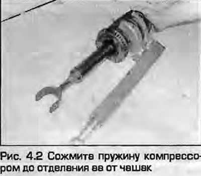
2. Install the spring compressors and compress the spring so that the lower coil moves away from the support cup (Fig. 4.2).
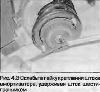
3. Unscrew the nut at the top of the stand, holding the rod with a hex key (Fig. 4.3). If you do not have a bent open-end wrench, you can use a high head with a side hole.
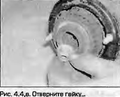
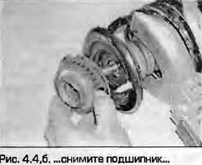
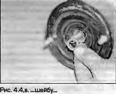
4. After unscrewing the nut, remove the upper support plate, washer and upper spring cup with support (fig. 4.4, a-g).
 |
 |
 |
 |
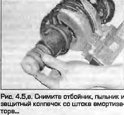
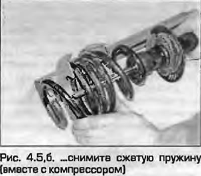
5. Remove the dust cover, rubber bump stop and protective cap from the shock absorber rod. Carefully remove the spring together with the compressors and put aside (fig. 4.5, a, b).
 |
 |
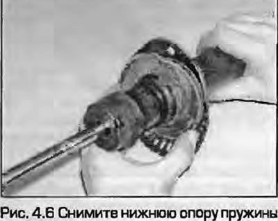
6. Remove the lower spring support (Fig. 4.6). If necessary, the lower spring cup can be removed from the strut by gentle blows with a rubber-coated hammer.
7. Check for shock absorber leaks. Check for wear or other damage to the rod along its entire length. Check for corrosion or other damage to the shock absorber body. Holding the shock absorber vertically, check the shock absorber's functionality by moving the rod up and down at full stroke, then at short strokes of 50...100 mm. In both cases, the resistance to movement should be soft and continuous. If the rod moves unevenly or if damage is obvious, replacement is necessary.
Note: Shock absorbers are replaced in pairs on the same axle to maintain suspension characteristics.
8. Inspect all components of the rack and replace any that are defective.
9. Install the lower spring cup, ensuring that the hole in it is positioned at an angle of 90° to the axis of the lower strut mounting bolt.
10. Install the lower spring seat into the groove of the lower cup.
11. Place the dust boot with the bump stop on the shock absorber rod of the strut. Make sure that the lower edge of the dust boot is correctly aligned with the base of the strut.
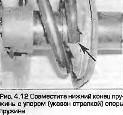
12. Install the compressed spring on the lower support cup. Make sure that the end of the lower spring coil rests against the protrusion on the spring support (Fig. 4.12).
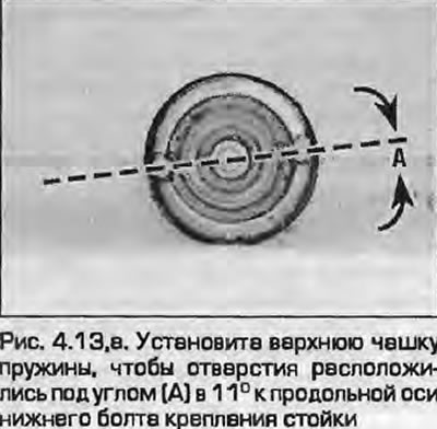
13. Install the upper spring seat and support cup, washer and upper seat so that the hole in the cup is at an angle of 11° to the longitudinal axis of the lower mounting bolt. If the assembly is carried out correctly, the upper spring end should be installed against the stop at the bottom of the upper seat (fig. 4.13, a-c).
 |
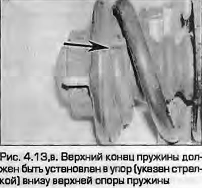 |
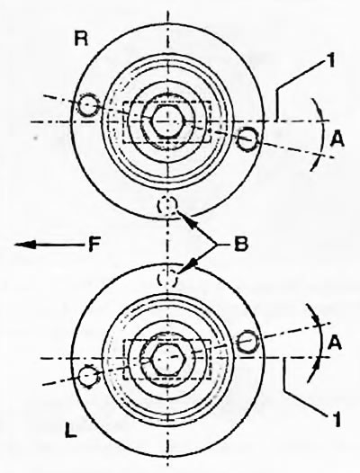
Fig. 4.13, b. Note the difference in the installation of angles between the left and right posts:
A. Angle = 11°±2°
B. Holes in the lower cup
F. Direction of vehicle movement "straight"
L. Left pillar
R. Right stand
1. Lower strut mounting bolt
14. Screw on the new stem nut. Using the method used for removal, hold the stem and tighten the nut to the specified torque.
15. Make sure the unit is assembled correctly (both ends of the spring should rest against the protrusions on the supports) and remove the spring compressors.
16. Install the stand on the vehicle as described in paragraph 3.