
2. Loosen the four wheel mounting bolts.
3. Jack up the front of the car. Remove the wheel.
4. Remove the brake caliper and mounting bracket as described in Section 9, do not disconnect the hydraulic hose. Secure the caliper.
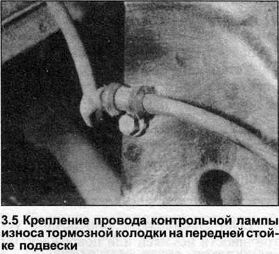
5. Disconnect the brake pad wear indicator lamp wire from the strut (photo) and, where applicable, the wheel speed sensor wire and the ABS wiring (see Section 9).
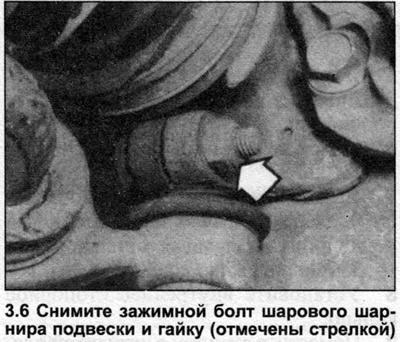
6. Unscrew and remove the ball joint clamp bolt and nut (photo).
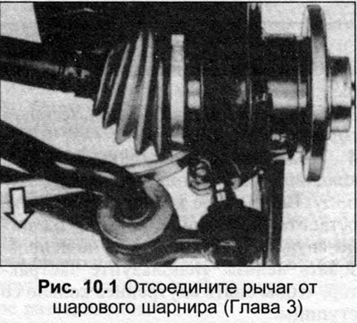
7. Using the ball joint release tool as described in Chapter 20, unscrew the nut and disconnect the end of the tip from the suspension strut.
8. Unscrew the drive shaft nut, pull the lever until the ball joint comes out of the rack.
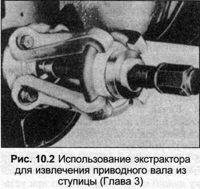
9. Press the drive shaft out of the hub assembly.
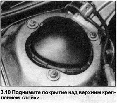
10. From inside the engine bay, lift up the plastic covering on the upper strut mount (photo).
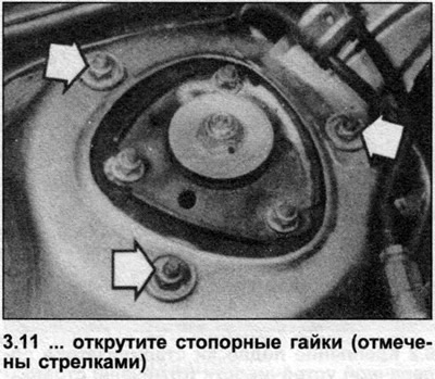
11. Supporting the suspension strut from below, unscrew the three outer nuts securing the upper strut mount to the body (photo).
12. Lower the stand and remove it.
13. Installation is carried out in reverse order. See. Section 8 when installing the drive shaft, and Section 9 when installing the brake caliper. Tighten all nuts and bolts to the tightening torque specified in Specifications. If the strut has been disassembled, check the front wheel camber angle as described in Chapter 29.
(The original article is posted on the resource: AUDIMANUAL)