
Table of contents: Removal and installation the rack ↓ Replacing the spring ↓ Removal and installation the strut… ↓
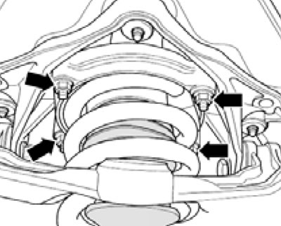
1. The installation details of the spring strut suspension are shown on illustrations 1.1b.
Removal and installation the rack
2. Remove the wheel, unscrew the bolt (2 in illustration 7.7 Chapter 7), disconnect the drive shaft from the main gear (3).
3. Loosen the tie rod end mounting nut and press it out of the steering knuckle (see Figure 7.8 in Chapter 7).
4. On models with a suspension height sensor, loosen the nut (2 in illustration 4.3). Separate the brake hose and bracket from the steering knuckle.
5. Unload the suspension (see Section 2).
6. Unscrew the upper arm mounting nut and press it out (see Figure 7.9 in Chapter 7).
7. Unscrew the nuts securing the rack to the body (see illustration).
5.7. Upper rack mount.
8. Unscrew the bolt nut (1 in illustration 7.7 Chapter 7) fastening the rack to the lower arm.
9. Lower the steering knuckle as far as necessary (see illustration).
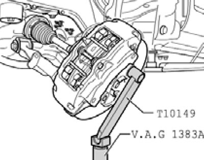
5.9. Lowering the steering knuckle.
10. Pull out the bolt (1 in illustration 7.7 Chapter 7) from the lower arm and remove the rack.
11. Installation is carried out in reverse order. On models with automatic headlight leveling, use the basic setting.
Replacing the spring
12. The suspension strut assembly details are shown in the illustration.
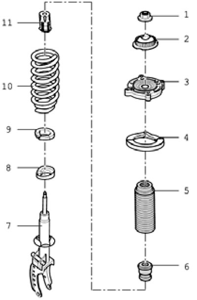
5.12. Suspension strut assembly details:
1 - Self-locking nut, replaceable, 60 Nm;
2 - Shock absorber support;
3 - Upper spring plate;
4 - Upper spring seat;
5 - Protective sleeve;
6 - Bumper;
7 - Shock absorber;
8 - Lower spacer;
9 - Lower spring seat;
10 - Spring;
11 - Protective cap.
13. Install suitable spring compressors (see illustration) and compress the spring enough to release its upper plate.
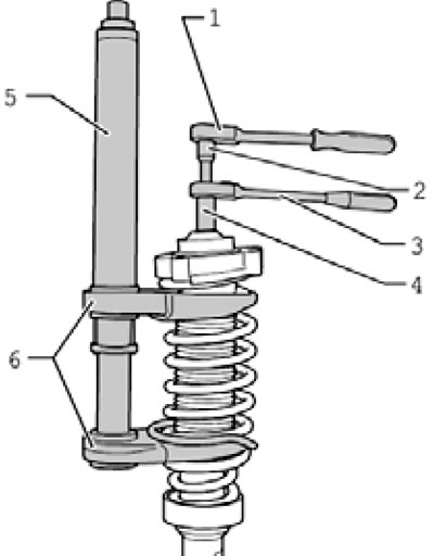
5.13. Removing the spring.
Unscrew the piston rod nut and remove the shock absorber support. Remove the upper spring plate with the protective sleeve, as well as the spring together with the compressor tool.
14. Install the upper saddle (And in the illustration) into the upper spring plate (B).
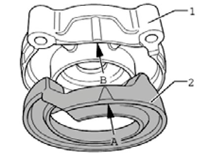
5.14. Installing the upper seat into the upper spring plate.
Place the compressed spring on the lower spacer with the rubber seat.
15. Install the protective sleeve and the upper spring plate on the piston rod so that the marks (With in the illustration) were located opposite the junction (1), and the central lines (A and B) were located parallel.
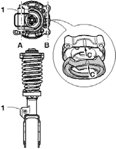
5.15. Position of the upper spring plate.
16. Make sure that the end of the spring coil rests against the upper seat (1 in the illustration), and the protective sleeve is fixed in the upper plate (2).
5.16. Installation position of the spring.
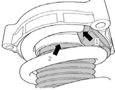
Install the support and tighten the new nut.
Removal and installation the strut bracket and upper arm
17. Remove the air intake chamber cover (see Section 19 of Chapter 1).
18. Remove the suspension strut (see above).
19. Support the lower suspension arm with a VW552 compressor and a T10038 strap (see illustration).
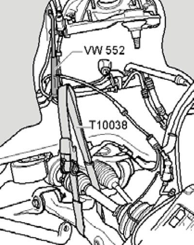
5.19. Fixing the lower suspension arm.
20. Remove the transmission jack with support T10149 (see illustration 5.9), unscrew the bolts (1-3 in the illustration) and remove the bracket.
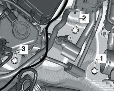
5.20. Removing the bracket.
21. Installation is carried out in reverse order.
[The original article is available on the website «AUDImanual»]